Imaging lens system

a lens system and image technology, applied in the field of image lens system, can solve the problems of insufficient utilization of the performance of the auto-focus mechanism, inability to achieve both high telecentricity and back focus distance at the same time, and difficulty in well-correcting such axial chromatic aberration, so as to achieve excellent optical performance, reduce size and weight, excellent productivity

Active Publication Date: 2007-01-02
ENPLAS CORP
View PDF9 Cites 2 Cited by
  • Summary
  • Abstract
  • Description
  • Claims
  • Application Information

AI Technical Summary

Benefits of technology

[0026]In the first aspect of the present invention, the diaphragm is disposed at a position closest to the object side and the first lens is a meniscus lens having a positive power with its concave surface facing the object side. With this, it is possible to secure a high telecentricity, back focus distance, and an excellent optical performance, to reduce the size and weight of the entire optical system, and to improve the productivity.
[0049]Moreover, in addition to the effects of the imaging lens system according to any one of the aspects 1–6, the imaging lens system according to the seventh aspect can achieve an imaging lens system that is suitable for more reduction of size and weight and an improvement in the productivity.

Problems solved by technology

However, the lens systems belonging to those types 1–3 have the following problems.
Thus, it is not possible to achieve both the high telecentricity and back focus distance at the same time.
In the lens system belonging to Type 3, it is difficult to well-correct such axial chromatic aberration, and the performance of the auto-focus mechanism cannot be fully utilized.
Therefore, it is the fact that there has not been proposed an effective lens system which can further improve the optical performance while being reduced in size and weight.

Method used


Image

  • Imaging lens system
  • Imaging lens system
  • Imaging lens system

Examples


examples

[0129]Next, EXAMPLES of the present invention will be described by referring to FIG. 2–FIG. 15.

[0130]In the EXAMPLES, F no denotes F number and r denotes the curvature radius of the optical surface (the center radius curvature in the case of a lens). Further, d corresponding to each optical surface denotes the distance from the respective optical surface to the next optical surface. Furthermore, nd denotes the index of refraction of the optical system when the d line (yellow) is irradiated, and vd denotes the Abbe number of each optical system also when the d line is irradiated.

[0131]k, A, B, C and D denote each coefficient in a following expression (16). Specifically, the shape of the aspherical surface of the lens is expressed by the following expression provided that the direction of the optical axis 8 is taken as the Z axis, the direction orthogonal to the optical axis 8 as the X axis, the traveling direction of light is positive, k is the constant of cone, A, B, C, D are the as...

first example

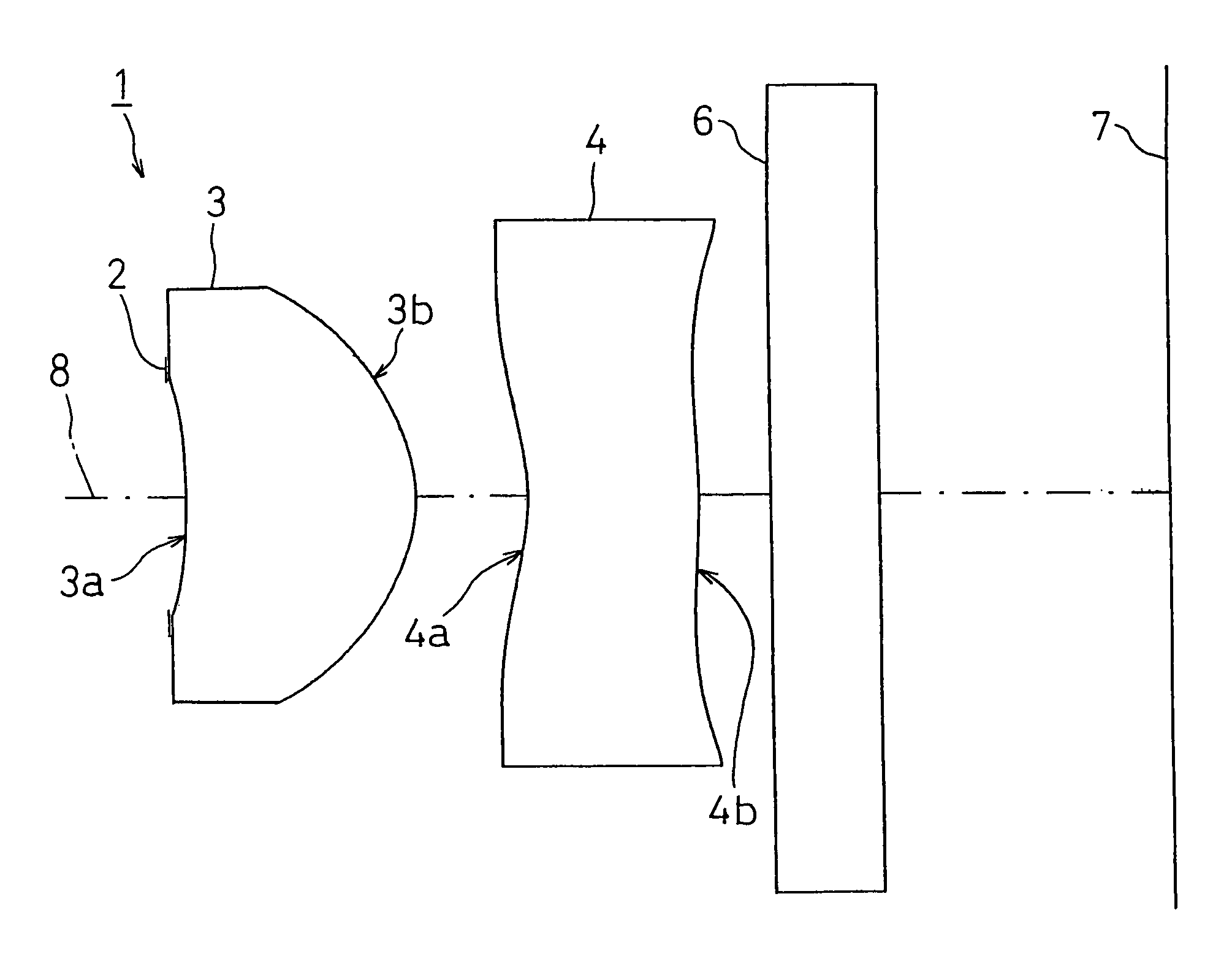
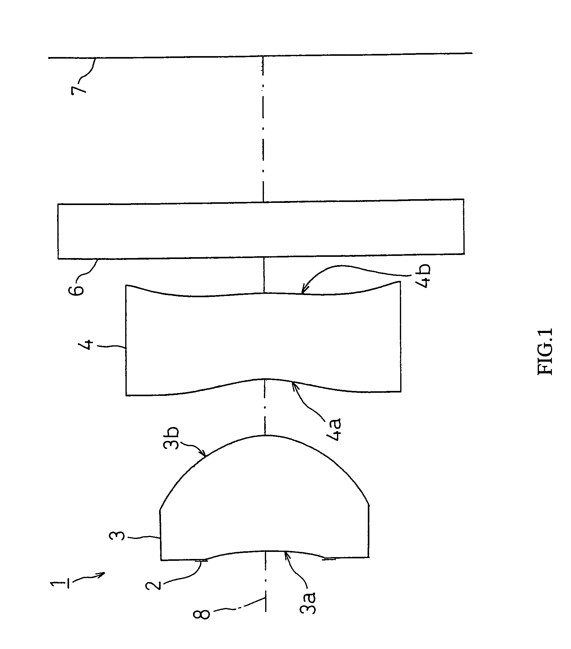
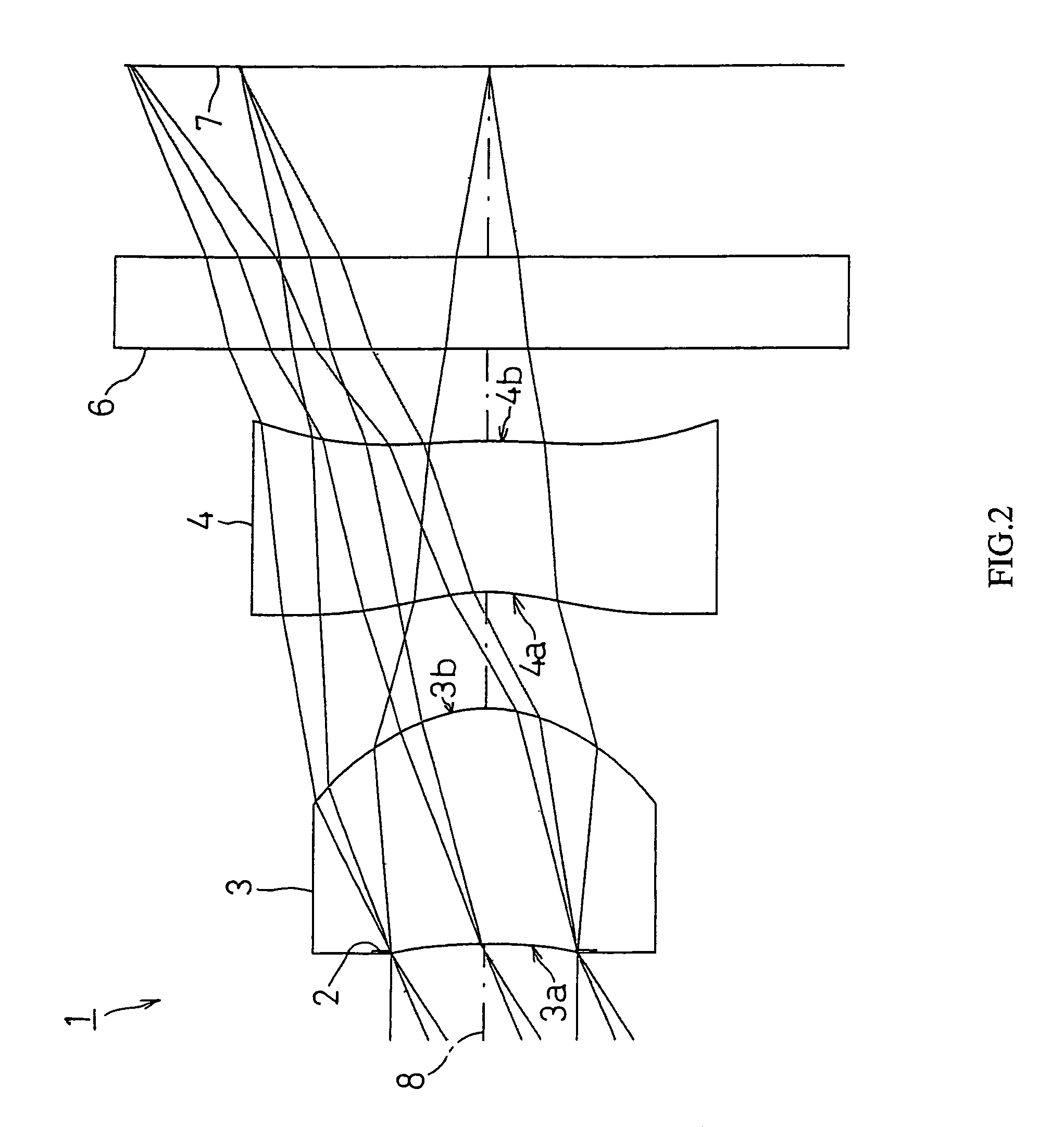
[0134]FIG. 2 shows FIRST EXAMPLE of the present invention. In FIRST EXAMPLE, like the imaging lens system 1 with the structure of FIG. 1, a diaphragm 2 was disposed on the object side of the first face 3a of the first lens 3, and a cover glass as a filter 6 is disposed between the second face 4b of the second lens 4 and an image taking surface 7.

[0135]The imaging lens system 1 of FIRST EXAMPLE was set under the following condition.

Lens Data

L=2.766 mm, fl=1.803 mm, f1=0.99 mm, f2=−2.02 mm, d1=0.762 mm, d2=0.377 mm, d3=0.482 mm, r1=−2.272 mm, r2=−0.480 mm, r3=−0.700 mm, r4=−2.145 mm, D=1.651, S=0.02, Bfl=1.115, F no=2.85

[0136]

Face Numberrdndvd(Object Point)1 (Diaphragm)∞0.0202 (First Face of First Lens)−2.2720.7621.53156.03 (Second Face of First Lens)−0.4800.3774 (First Face of Second Lens)−0.7000.4921.58530.05 (Second Face of Second Lens)−2.1450.3006 (First Face of Cover Glass)∞0.3001.51664.07 (Second Face of Cover Glass)∞(Image surface)FaceNum-berkABCD2 0.000−0.985E 0.114E+1−0.237E+...

second example

[0140]FIG. 4 shows SECOND EXAMPLE of the present invention. In SECOND EXAMPLE, like the imaging lens system 1 with the structure shown in FIG. 1, a diaphragm 2 was disposed on the object side of the first face 3a of the first lens 3, and a cover glass as a filter 6 is disposed between the second face 4b of the second lens 4 and the image taking surface 7.

[0141]The imaging lens system 1 of SECOND EXAMPLE was set under the following condition.

Lens Data

L=2.746 mm, fl=1.798 mm, f1=1 mm, f2=−2.01 mm, d1=0.761 mm, d2=0.384 mm, d3=0.486 mm, r1=−2.355 mm, r2=−0.483 mm, r3=−0.700 mm, r4=−2.145 mm, D=1.651, S=0.02, Bfl=1.095, F no=2.85

[0142]

Face Numberrdndvd(Object Point)1 (Diaphragm)∞0.0202 (First Face of First Lens)−2.3550.7611.53156.03 (Second Face of First Lens)−0.4830.3844 (First Face of Second Lens)−0.7000.4861.58530.05 (Second Face of Second Lens)−2.1450.2006 (First Face of Cover Glass)∞0.3001.51664.07 (Second Face of Cover Glass)∞(Image surface)FaceNum-berkABCD2 0.000−0.105E+1 0.194E+...


PUM


Abstract

It is to provide an imaging lens system which, while reduced in size and weight, can fully meet the demand for more improvement in the optical performance and also improvement in the productivity. The imaging lens system comprises, in order from an object side towards an image surface side, a diaphragm, a first lens which is a meniscus lens having a positive power whose concave surface facing the object side, and a second lens which is a meniscus lens having a negative power whose convex surface facing the image surface side, wherein the Abbe number of the second lens is set smaller than the Abbe number of the first lens.

Description

BACKGROUND OF THE INVENTION[0001]1. Field of the Invention[0002]The present invention relates to an imaging lens system and, particularly, to an imaging system of two-lens structure, which is capable of reducing the size and weight and improving the optical performance and productivity. The imaging system is used for an image-taking device that forms images of objects such as scenery and human figures on an image taking surface of a solid image sensor element such as a CCD, CMOS, etc., which is mounted on a portable computer, a television telephone, a cellular phone, and the like.[0003]2. Description of the Related Art[0004]Recently, there has been an increasing demand for reducing the size and weight and improving the optical performance (high resolution of the solid image sensor element, etc) of an image-taking device (camera) that utilizes a solid image sensor element such as a CCD, CMOS, or the like, which is mounted on a portable telephone, a portable computer, and a television...

Claims


Application Information

Patent Timeline
Patent Type & Authority Patents(United States)
IPC IPC(8): G02B9/04
CPCG02B13/003G02B9/10G02B3/00
Inventor SAITO, TOMOHIRO
Owner ENPLAS CORP
Why Eureka
Try Eureka