Combining a clock signal and a data signal

a clock signal and data signal technology, applied in the direction of synchronisation signal speed/phase control, instruments, static indicating devices, etc., can solve the problems of system transmitting both a data signal and a clock signal over the clock channel, and the addition of data signals cannot be transmitted over the clock channel using this system, so as to minimize or reduce the interference between symbols of the combined signal transmitted over a band-limited channel

Active Publication Date: 2007-01-02
SILICON IMAGE INC
View PDF10 Cites 24 Cited by
  • Summary
  • Abstract
  • Description
  • Claims
  • Application Information

AI Technical Summary

Benefits of technology

[0021]performing pre-emphasis to the combined signal, so that inter-symbol interference

Problems solved by technology

However, because only the clock signal is transmitted over the clock channel, additional signals, such as data signals for example, cannot be transmi

Method used


Image

  • Combining a clock signal and a data signal
  • Combining a clock signal and a data signal
  • Combining a clock signal and a data signal

Examples


Embodiment Construction

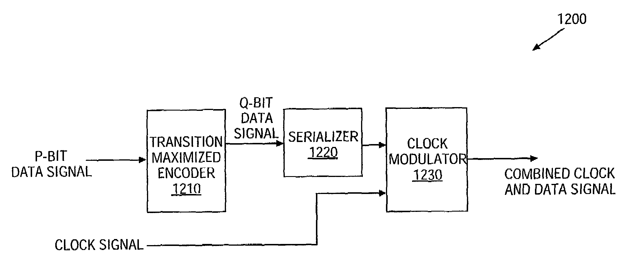
[0087]A method and system to combine a data signal with a clock signal and to transmit the combined signal are disclosed. The combined clock and data signal are transmitted over a clock channel. This increases the amount of bandwidth that is available in the clock channel. In one embodiment, the data signal is encoded, and the encoded data signal is combined with the clock signal. The encoding of the data signal causes some of the energy components of the encoded data signal to move to higher frequencies, so that a low pass filter can attenuate them. The low pass filter can then recover the clock signal from the combined signal, and output the recovered signal to other devices.

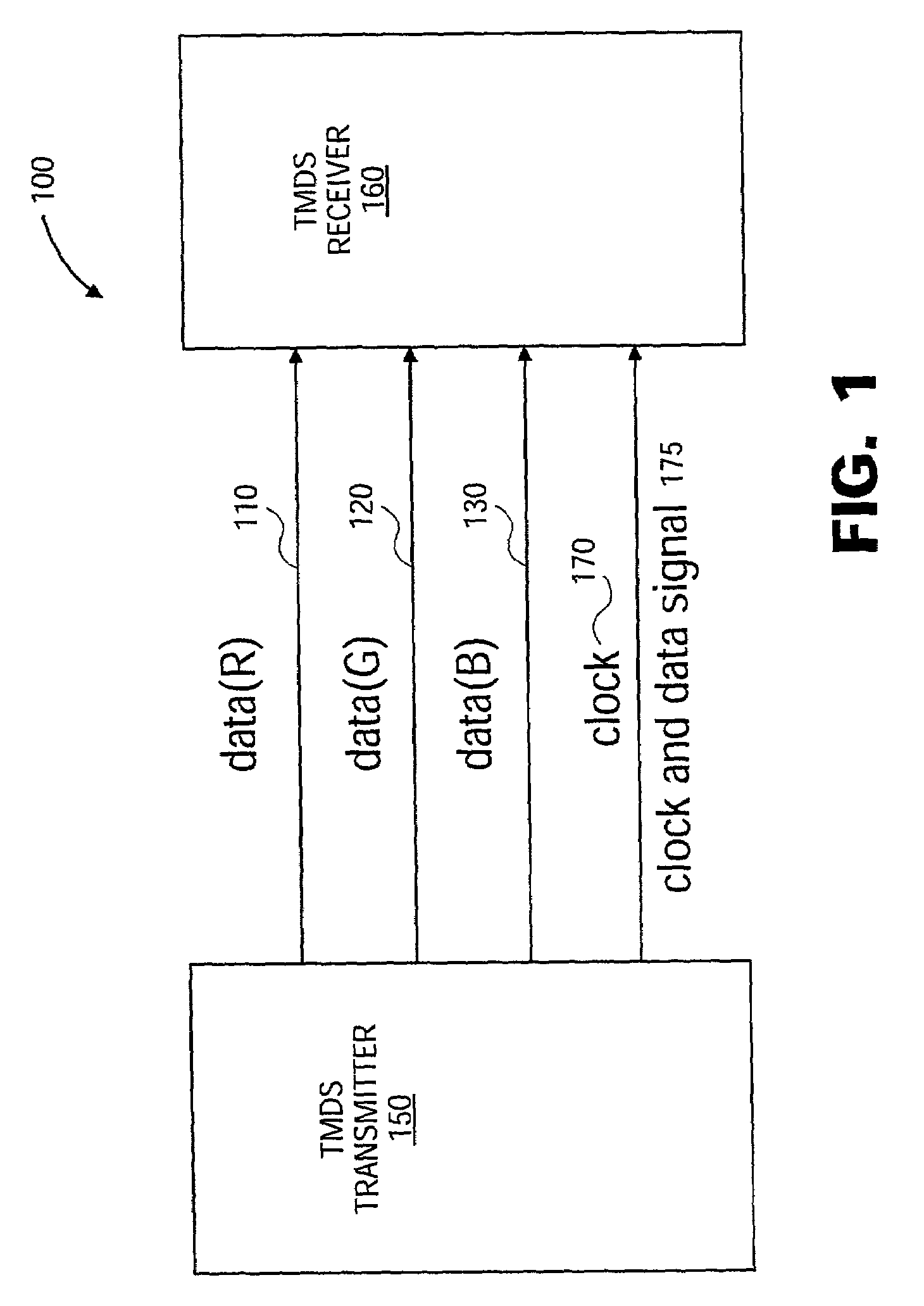
[0088]An example of a system that combines the clock signal and the data signal is a transition-minimized differential signaling (TMDS) system, which is described in U.S. application Ser. No. 09 / 393,235, entitled “A System And Method For Sending And Receiving Data Signals Over A Clock Signal Line,” became an U...


PUM


Abstract

A method of transmitting data in a system including at least one data channel and a separate clock channel is disclosed. The method involves combining a clock signal to be transmitted on the clock channel with a data signal to generate a combined clock and data signal. In one embodiment, the data signal has been generated from data words using an encoding scheme that shifts an energy spectrum of the data signal away from an energy spectrum of the clock signal. In another embodiment, the clock signal has a plurality of pulses each having a front edge and a back edge, and the data signal is modulated onto the clock signal by moving at least one edge (i.e. front or back or both) of the plurality of pulses, thereby to create a combined clock and data signal.

Description

CROSS-REFERENCE TO RELATED APPLICATIONS[0001]This application claims priority under 35 U.S.C. § 120 from co-pending U.S. application Ser. No. 09 / 393,235, filed on Sep. 9, 1999 by Gyudong Kim, Minkyu Kim, and Seung Ho Hwang, entitled “A System And Method For Sending And Receiving Data Signals Over A Clock Signal Line,” which is fully incorporated into this application by reference; and this application claims priority from and the benefit of U.S. Provisional Patent Application No. 60 / 276,672, filed on Mar. 16, 2001, entitled “Encoding Scheme for a Phase Modulated Clock Signal,” which is fully incorporated into this application by reference.BACKGROUND OF THE INVENTION[0002]1. Field of the Invention[0003]The present invention relates to transmitting clock and data signals.[0004]2. Description of the Background Art[0005]The digital visual interface DVI 1.0 Specification, Digital Display Working Group [online], Apr. 2, 1999 [retrieved Mar. 15, 2001], retrieved from the Internet:<URL:h...

Claims


Application Information

Patent Timeline
IPC IPC(8): H04L7/00H03L7/099G09G5/00H04L5/06H04L7/02H04L7/027H04L7/04H04L25/49
CPCH04L5/06H04L25/4902H04L7/0008G09G5/006H04L7/0054H04L7/027H04L7/02
Inventor KIM, GYUDONGKIM, OOKKIM, MIN-KYUKIM, BRUCEHWANG, SEUNG HO
Owner SILICON IMAGE INC
Why Eureka
Try Eureka