

Face image recording system
a recording system and face technology, applied in the field of face image recording system, can solve the problems of inability to accurately identify a person, and inability to achieve the person identification method using biomedical features mechanically, etc., to achieve highly convenient person authentication, reduce system installation cost, and facilitate us
- Summary
- Abstract
- Description
- Claims
- Application Information
AI Technical Summary
Benefits of technology
Problems solved by technology
Method used
Image

Examples
third embodiment
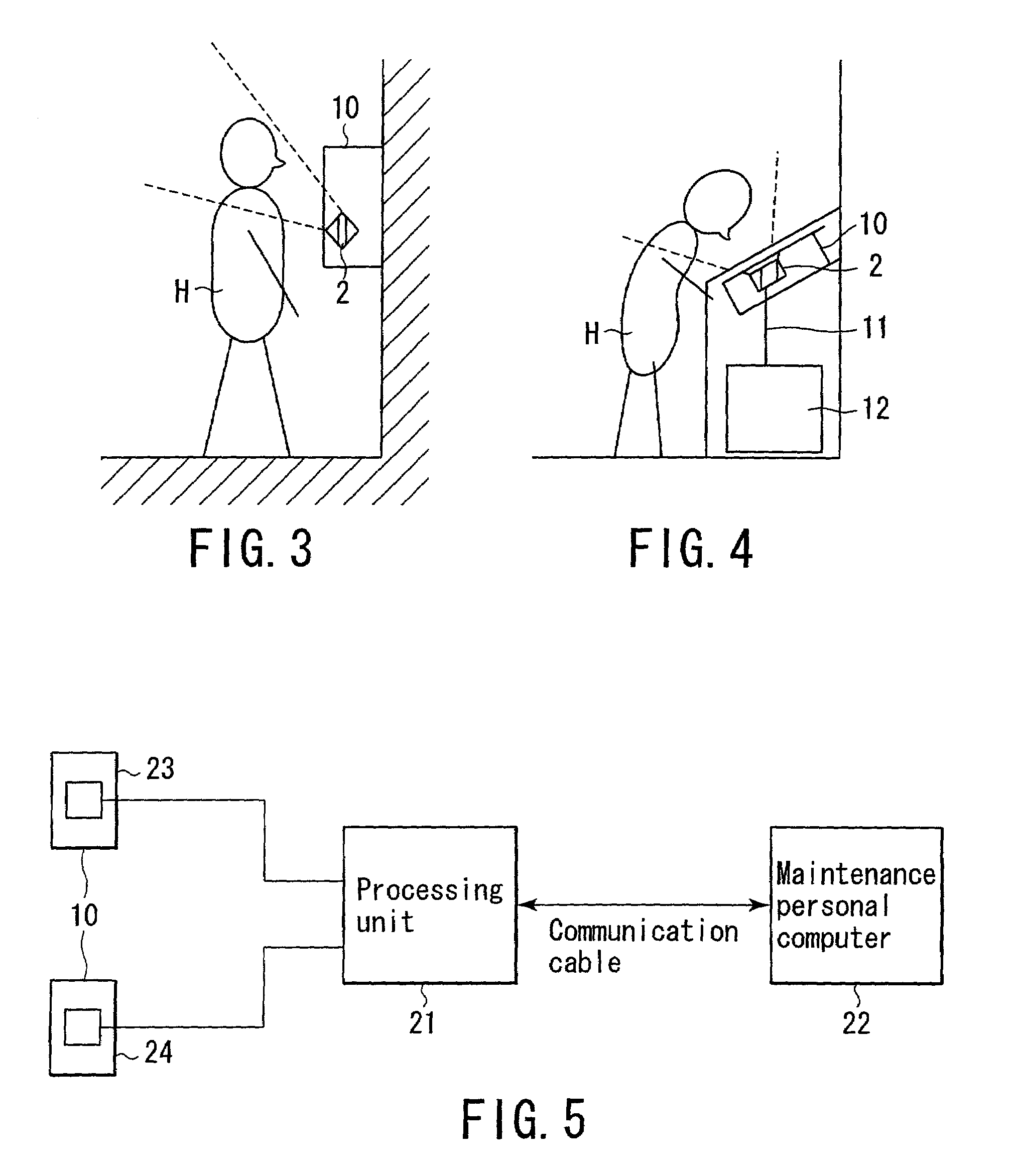
[0061]FIG. 5 is a block diagram showing an arrangement when the user interface units 10 are installed in a plurality of locations such as doors 23 and 24. In this arrangement shown in FIG. 5, the user interface units 10 at the doors 23 and 24 are connected to a processing unit 21. This processing unit 21 is connected to a maintenance personal computer 22 via a communication cable. Note that an arrangement in which a maintenance personal computer is connected to a face image recording apparatus will be described in detail later in the
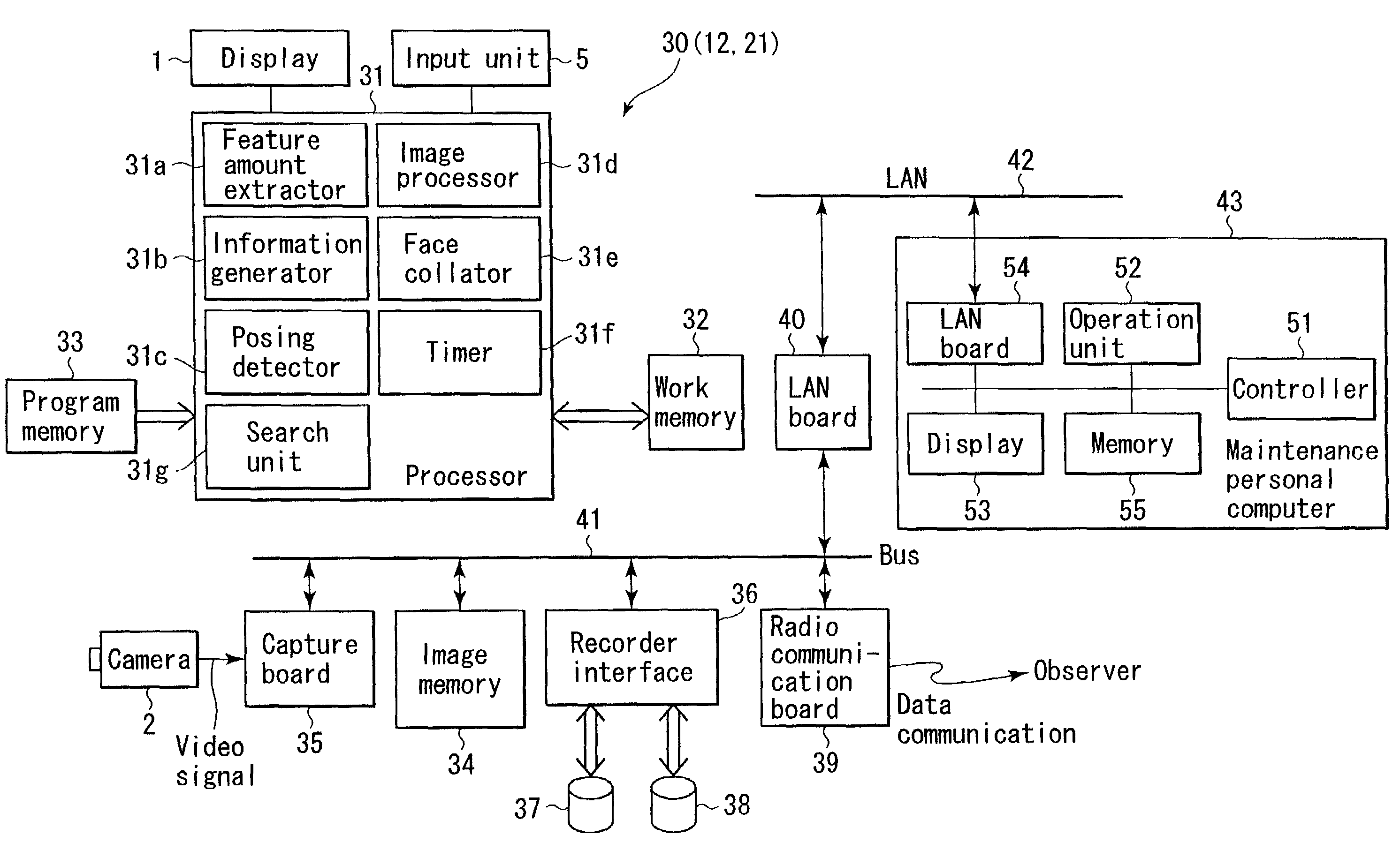
[0062]FIG. 6 is a block diagram showing the overall arrangement as a control system of the face image recording apparatus.
[0063]As shown in FIG. 6, a processing unit 30 (12, 21) of the face image recording apparatus includes a processor 31, work memory 32, program memory 33, image memory 34, capture board 35, recorder interface 36, recorder 37, collating dictionary 38, radio communication board 39, LAN board 40, and bus 41.
[0064]The processor 31 controls...
first embodiment
[0076]The first embodiment will be described below.
[0077]In this first embodiment, a face image of a user is stored as log data by the face image recording apparatus configured as above. Note that the face image recording apparatus can be solely installed in this first embodiment. This face image recording apparatus will be called a standalone single function type because the apparatus has a single function of recording face images.
[0078]FIGS. 7 and 8 are flow charts for explaining the whole flow of a face image recording process.
[0079]First, when the camera 2 photographs the face of a user, the capture board 35 sequentially stores (buffers) the color face images (digital data) from the camera 2 into the image memory 34. The processor 31 sequentially reads out these images buffered in the image memory 34 onto the work memory 32. The processor 31 extracts feature amounts from the images read out onto the work memory 32. If a face image can be extracted by this feature amount extracti...
second embodiment
[0127]The second embodiment will be described below.
[0128]The second embodiment is a modification of the first embodiment. This second embodiment is implemented by a face image recording apparatus having an arrangement as shown in FIG. 6. In the second embodiment, feature amounts of the face of a registrant are registered beforehand in a face collating dictionary 38 in the configuration of the face image recording apparatus shown in FIG. 6. Also, in this second embodiment a processor 31 functions as a face collator 31c by using a control program stored in a program memory 33.
[0129]FIGS. 12 and 13 are flow charts for explaining the second embodiment. This processing of the second embodiment shown in FIGS. 12 and 13 includes a face image collating process in addition to the processing of the first embodiment explained in FIGS. 7 and 8. That is, steps S41 to S54 of the processing shown in FIGS. 12 and 13 are the same as steps S1 to S14 of the processing shown in FIGS. 7 and 8. Therefor...
PUM
 Abstract
Description
Claims
Application Information