Image compression with tile alignment

a tile alignment and image compression technology, applied in the field of image compression apparatus, image decompression apparatus, image compression method, can solve the problems of limited methods, image quality deterioration in jpeg files is no longer negligible, and the “borders of tiles” stand out, so as to control the deterioration of image quality

Inactive Publication Date: 2007-01-02
RICOH KK
View PDF5 Cites 70 Cited by
  • Summary
  • Abstract
  • Description
  • Claims
  • Application Information

AI Technical Summary

Benefits of technology

[0036]A more specific object of the present invention is to provide an image compression apparatus, image decompression apparatus, image compression method, image decompression method, computer program product for causing a computer to function as the image compression apparatus or one or more of parts of the image compression apparatus, the image decompression apparatus or one or more of parts of the decompression apparatus, and a computer-readable recording medium recording a computer readable program code embodied therein for causing a computer to function as the image compression apparatus or one or more of the parts of the image compression apparatus, the image decompression apparatus or one or more of the parts of the image decompression apparatus that can drastically reduce “elicitation of borders of tiles” that occurs when decoding image data obtained by performing a lossy (irreversible) compression on an original image under a condition of high compression rate of the original image.
[0040]In the above-mentioned aspect of the present invention, the above-described solution for a still image is applied to a moving image. According to this aspect of the present invention, it is possible to determine a tile size of an original image for each frame, or each component in each frame. In addition, the tile size can be determined arbitrarily. Thus, the borders of the tiles do not overlap each other temporally (in time) nor spatially. As a result, it is possible to control the elicitation of borders of tiles so as to be substantially low.
[0046]According to the above-mentioned aspect of the present invention, it is possible to decompress a compressed image on which a compression process is performed by the above-described image compression apparatus.
[0054]According to the above-mentioned aspects of the present invention, it is possible to perform tile division of an original image for each component, each frame or each component in each frame. In addition, the sizes of the rectangular tiles are determined arbitrarily. Thus, it is possible to control the elicitation of borders of tiles and to improve image quality both in still images and moving images.
[0059]According to the above-mentioned aspects of the present invention, it is possible to carry out a program having functions of the image compression process and the image decompression process. Thus, it is possible to control deterioration in image quality due to tile division.

Problems solved by technology

In other words, deterioration of image quality in JPEG files is becoming no longer negligible.
Therefore, at the present time, only limited methods that highly depend on hardware such as ASIC and DSP can realize the function.
However, according to the above-described conventional technology, there is a problem in that “borders of tiles” stand out when the compression / decompression process is performed under a condition where the compression rate is high.
Actually, volume of data of an image becomes very large when an original image that is a target of the compression / decompression process is spatially very large, or when each color component has a deep gradation level.
Such a technical problem is newly raised as the above-described demand in the market for high-definition still images become higher.
Additionally, process time required for compression or decompression also becomes very long.
However, the new problem, that is, the above-described “elicitation (or revealing) of borders of tiles” has arisen due to dividing an original image into tiles.

Method used


Image

  • Image compression with tile alignment
  • Image compression with tile alignment
  • Image compression with tile alignment

Examples


Embodiment Construction

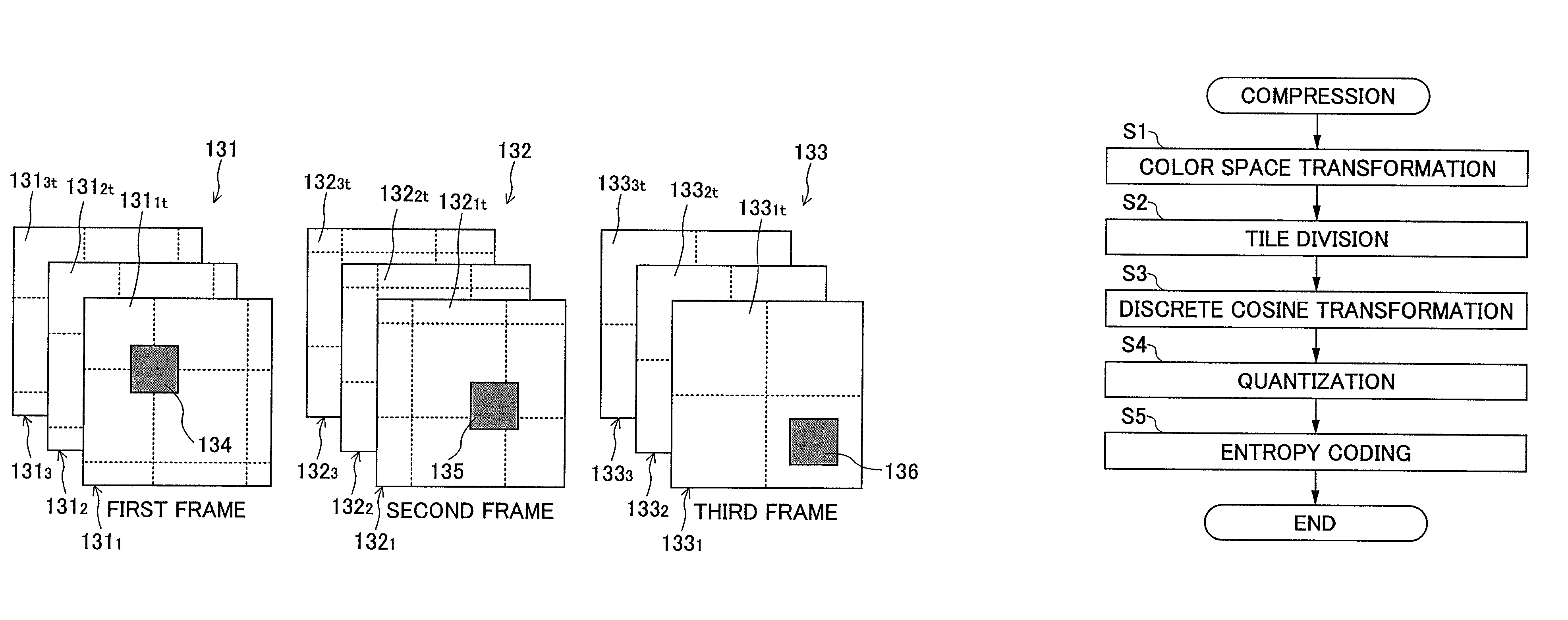
[0082]FIG. 6 is a schematic diagram for explaining tile division for each component of a still image in an image compression / decompression apparatus and image compression / decompression method according to one embodiment of the present invention.

[0083]The image compression apparatus according to this embodiment includes a tile size determiner, an image divider, and an image compression processor. The tile size determiner determines the size of a rectangular tile of each component for a still image having a plurality of components. The image divider divides an image using rectangular tiles (referred to as “tile”, hereinafter) determined by the tile size determiner. The image compression processor performs an irreversible compression process on the still image divided by the image divider. It should be noted that the component includes a zone component (not limited to a wavelength in a visible region) such as a spectrum band as well as a component of color space such as RGB, YUV, YCbCr...


PUM


Abstract

An image compression apparatus includes a tile size determiner, an image divider and an image compression processor. The tile size determiner determines an arbitrary size of a rectangular tile for each component of a still image having a plurality of components. The image divider divides the image using the rectangular tiles the sizes of which are determined by the tile size determiner. The image compression processor performs an irreversible compression process on the image divided by said image divider.

Description

BACKGROUND OF THE INVENTION[0001]1. Field of the Invention[0002]The present invention generally relates to an image compression apparatus, an image decompression apparatus, an image compression method, an image decompression method, a computer program product, and a computer-readable recording medium recording a computer-readable program.[0003]2. Description of the Related Art[0004]As image input technology and output technology therefor progress, color still images with high definition are in great demand these days. Taking a digital camera (DC) as an example of an image input apparatus, price reduction of a high-performance charge coupled device (CCD) having the number of pixels of three million or more has been achieved, and the high-performance CCDs have been widely used for DC products at popular prices. The CCD is greatly indebted to progress in silicone processing or semiconductor device technology for the improvement of its performance. According to the progress, the trade-o...

Claims


Application Information

Patent Timeline
Patent Type & Authority Patents(United States)
IPC IPC(8): G06K9/36G06K9/40H04N11/04G06T9/00H03M7/30H03M7/40H04N1/41H04N19/102H04N19/136H04N19/162H04N19/172H04N19/186H04N19/46H04N19/60H04N19/625H04N19/63H04N19/70H04N19/86H04N19/91
CPCG06T9/007
Inventor SANO, YUTAKASAKUYAMA, HIROYUKIKODAMA, TAKU
Owner RICOH KK
Why Eureka
Try Eureka