Carriage structure for image-reading device

a technology of image-reading device and carriage, which is applied in the direction of electrographic process apparatus, printers, instruments, etc., can solve the problems of reducing the rigidity of affecting the accuracy of positioning of the optical elements carried by the carriage, and the image data acquired is not faithful to the document being scanned. , to achieve the effect of reducing the bowing of the carriage, increasing the rigidity of the reinforcing sheet metal, and reducing the rigidity of the rigidity of th

Inactive Publication Date: 2007-01-02
FUJI PHOTO OPTICAL CO LTD
View PDF2 Cites 0 Cited by
  • Summary
  • Abstract
  • Description
  • Claims
  • Application Information

AI Technical Summary

Benefits of technology

[0004]The present invention relates to a carriage structure in an image-reading device such as a scanner or the like that scans images formed on an original document and acquires image data while an optical unit mounted on the carriage is moved along the original document. The invention provides a carriage structure for an image-reading device in which the carriage is made thinner than prior art carriages for image-reading devices. This enables the image-reading device itself to be made thinner.
[0006]Because the shape of the carriage can be maintained by using reinforcing sheet metal, bowing of the carriage can be minimized. Accordingly, the optical path lengths at the edge verus at the center of the carriage can be maintained substantially equal so that image data that is faithful to that of the document being scanned can be acquired, thereby enabling a clear image to be reproduced. Thus, the carriage structure according to the invention is formed so as to have a suitable rigidity.
[0007]In addition, the carriage structure for an image-reading device may have the reinforcing sheet metal bent into a suitable shape, as will now be discussed in detail. By bending the reinforcing sheet metal into a suitable shape, the rigidity of the reinforcing sheet metal is increased. Consequently, it is possible to limit the amount of bowing of the carriage. As a suitable shape of the reinforcing sheet metal, it is possible to employ an L-shape, a V-shape, a crank shape, or a titled V-shape. Having selected one of these shapes for the reinforcing sheet metal, it is easy to accomplish the bending process to form the reinforcing sheet metal into such a shape.

Problems solved by technology

Designing the carriage to have a sufficient thickness in order to properly support such a long carriage becomes an impediment to the objective of making the carriage thinner.
Such strain, or bowing of the carriage, will jeopardize the accuracy in positioning of the optical elements carried by the carriage.
Additionally, there is a concern that the length of the light paths at the edge and at the center of the carriage may become different, so that the image data acquired is not faithful to the document being scanned.
This will cause images, obtained by reproducing the image data, to be unclear.

Method used


Image

  • Carriage structure for image-reading device
  • Carriage structure for image-reading device
  • Carriage structure for image-reading device

Examples


first embodiment

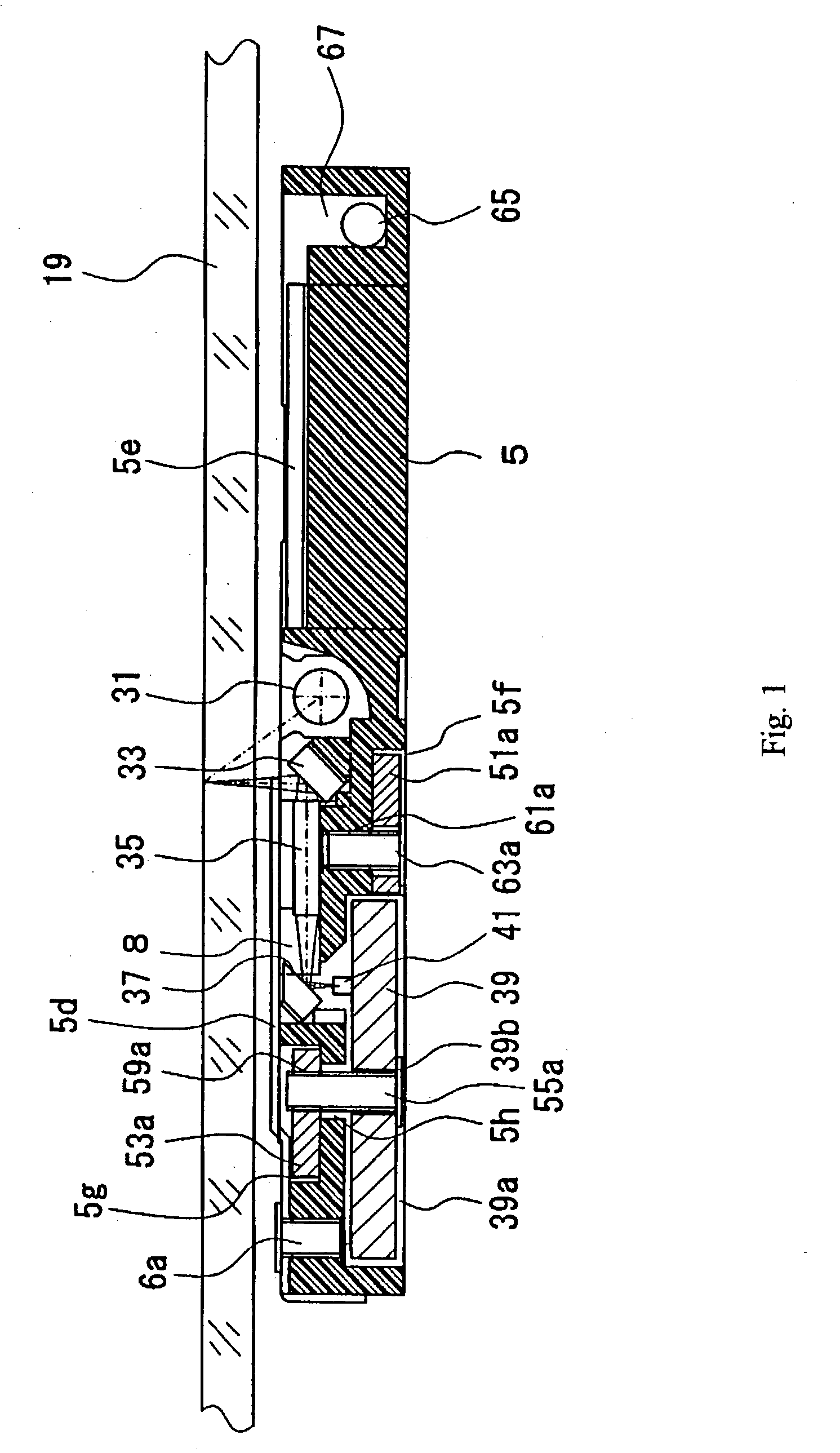
[0025]With the carriage structure the rigidity of the carriage 5 is increased because the reinforcing sheet metal members 51a and 53a are incorporated into the carriage 5. Through this, bowing of the carriage 5 is prevented even when the device is made thinner. In particular, because the first reinforcing sheet metal member 51a is positioned below the rod lens array 35 that guides the light reflected from the original document to the photoelectric conversion device 41, bowing of the rod lens array 35 is prevented, and changing of the optical path length from the original document surface to the photoelectric conversion device 41 between the edges and the center of the carriage 5 is prevented. In other words, because the rod lens array 35 is composed of column-shaped rod lenses arranged in parallel, bowing can readily occur between adjacent rod lenses, but by using the first reinforcing sheet metal member 51a, bowing can be prevented.

second embodiment

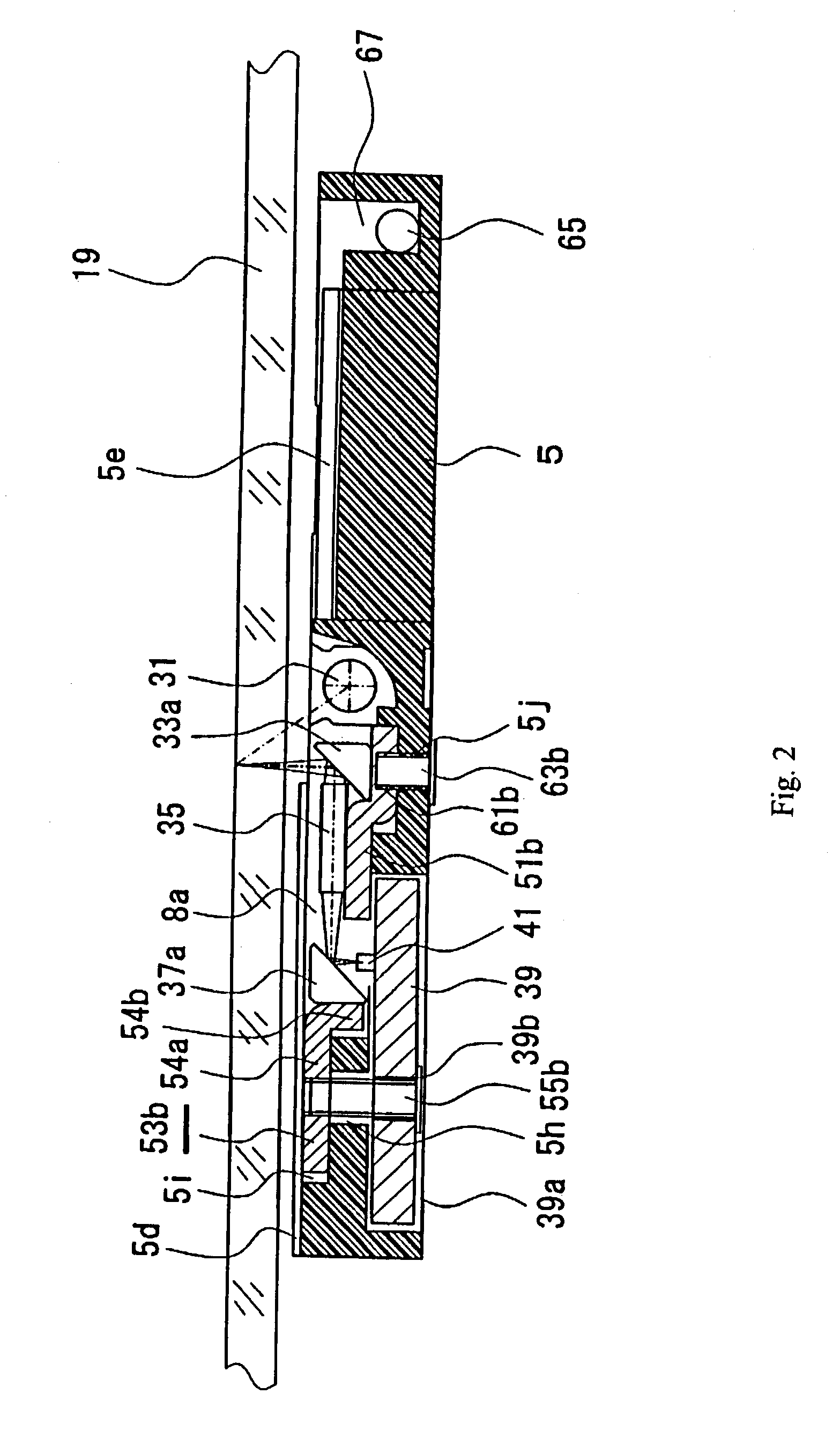
[0026]The carriage structure shown in FIG. 2 will be explained next. Parts that are the same as in the embodiment shown in FIG. 1 are labeled with the same reference numbers. As shown in FIG. 2, the second reinforcing sheet metal member 53b is bent so as to have a substantially L-shaped cross-section, and the leg 54a on the longer side thereof is seated in second indentation 5i. The second indentation 5i is linked to the unit holder 8a in which is seated the optical unit that includes the second reflective mirror 37a, and the leg 54b on the short side of the L-shaped second reinforcing sheet metal member 53b is positioned inside the unit holder 8a, the tip thereof pointing downward.

[0027]In addition, the first reinforcing sheet metal member 51b is formed with the cross-section substantially crank-shaped, as shown in FIG. 2, and is positioned on the bottom surface of the unit holder 8a. The bottom surface of the unit holder 8a has a step formed to coincide with the substantially cra...

third embodiment

[0033]With the carriage structure the first reinforcing sheet metal member 51c and the second reinforcing sheet metal member 53c are both bent in the center in the width-wise direction. Because the reinforcing sheet metal members 51c and 53c can resist a larger bending moment than the reinforcing sheet metal members 51a and 53a formed in a strip shape, it is possible to maintain the flatness of the carriage with greater certainty.

[0034]In addition, in the carriage structure according to the third embodiment, the first reflective mirror 33c is attached to the first reinforcing sheet metal member 51c and the second reflective mirror 37c is attached to the second reinforcing sheet metal member 53c. Therefore, it is possible to attach the reinforcing sheet metal members 51c and 53c to the carriage 5 with the reflective mirrors 33c and 37c being pre-attached. In particular, in making the carriage 5 thinner and lighter in weight, the reflective mirrors 33c and 37c are made to be extremel...


PUM


Abstract

A carriage structure is disclosed for an image-reading device that acquires image data from a document while an optical unit is moved along the document. The carriage structure is formed of molded plastic with reinforcing sheet metal members incorporated therein, and the optical unit, including a light source, photoelectric conversion device and optical elements, are positioned at predetermined positions on the carriage and are supported by, and incorporated within, the carriage structure. The reinforcing sheet metal members are bent into at least one of an L-shape, a V-shape, a crank shape, or a tilted V-shape in order to achieve a desired rigidity for the carriage structure.

Description

BACKGROUND OF THE INVENTION[0001]Among prior art image-reading devices (sometimes termed “image scanners” or simply “scanners”), there are those in which an optical unit, which includes optical elements such as mirrors and lenses which guide light that is reflected from a document to a photoelectric conversion device, is moved along a document in order to obtain image data from the document. The optical unit is incorporated into a carriage and a driving mechanism causes the carriage to move. For example, a driving belt such as a timing belt or the like may be moved back and forth by the output rotation of a driving motor, with the carriage being connected to the driving belt. In addition, to guide the movement of the carriage, a guide rod extends in the direction of movement (i.e., in the lengthwise direction) and is connected to the carriage.[0002]The carriage is molded of plastic (i.e., a synthetic resin) and is formed into a suitable shape. A light source, photoelectric conversio...

Claims


Application Information

Patent Timeline
Patent Type & Authority Patents(United States)
IPC IPC(8): G03G15/30G03B27/50G03B27/00H04N1/10H04N1/107
CPCG03B27/00
Inventor HAYASHI, EIICHI
Owner FUJI PHOTO OPTICAL CO LTD
Why Eureka
Try Eureka