System for detecting and compensating for aerodynamic instabilities in turbo-jet engines

a technology of aerodynamic instability and turbo-jet engines, which is applied in the direction of machines/engines, efficient propulsion technologies, light and heating apparatus, etc., can solve the problems of increasing the probability and still affecting technology. , to achieve the effect of reducing the possibility of stalling or surg

Inactive Publication Date: 2007-01-09
KULITE SEMICON PRODS
View PDF43 Cites 35 Cited by
  • Summary
  • Abstract
  • Description
  • Claims
  • Application Information

AI Technical Summary

Problems solved by technology

While jet engine technology has advanced one of the safest and fastest growing markets for mass transportation, the technology still suffers from problems caused by rotational stall and surge caused by changes in the air flow rates through the compressor.
Such problems can be magnified by environments where the speed of the engine and the air speed in which the engine operates are changed.
While providing an optimum operating environment can reduce the occurrence of stall and surge, these same problems have arisen in gas turbine engines implemented in the power generation field where the engine are operated at generally constant speeds with a controlled air flow environment.
The problem is that stall and surge are more likely to occur when the engine is operated at or near its optimum operating speed.
While such solutions have worked well in implementations relating to turbine engines relating to power systems, such solutions have been hampered in the use of such solutions for jet engines.
One problem has been the installation of sensors to detect the air flow conditions.
The operational environment of the turbine engine causes the sensors to be subjected to extreme temperatures and vibrational conditions.
While the sensors in gas turbines for power generation and the like may be mounted in a way to isolate the sensor from such harsh conditions, the turbine engines used in jet aircraft have weight and aerodynamic considerations that make such techniques impractical.
Such materials help to incrementally increase efficiency and reduce weight; however, such materials have also increased vibration encountered in the engine.
The result of these advances is the operating conditions in which the sensors must operate have become more severe.

Method used


Image

  • System for detecting and compensating for aerodynamic instabilities in turbo-jet engines
  • System for detecting and compensating for aerodynamic instabilities in turbo-jet engines
  • System for detecting and compensating for aerodynamic instabilities in turbo-jet engines

Examples


Embodiment Construction

)

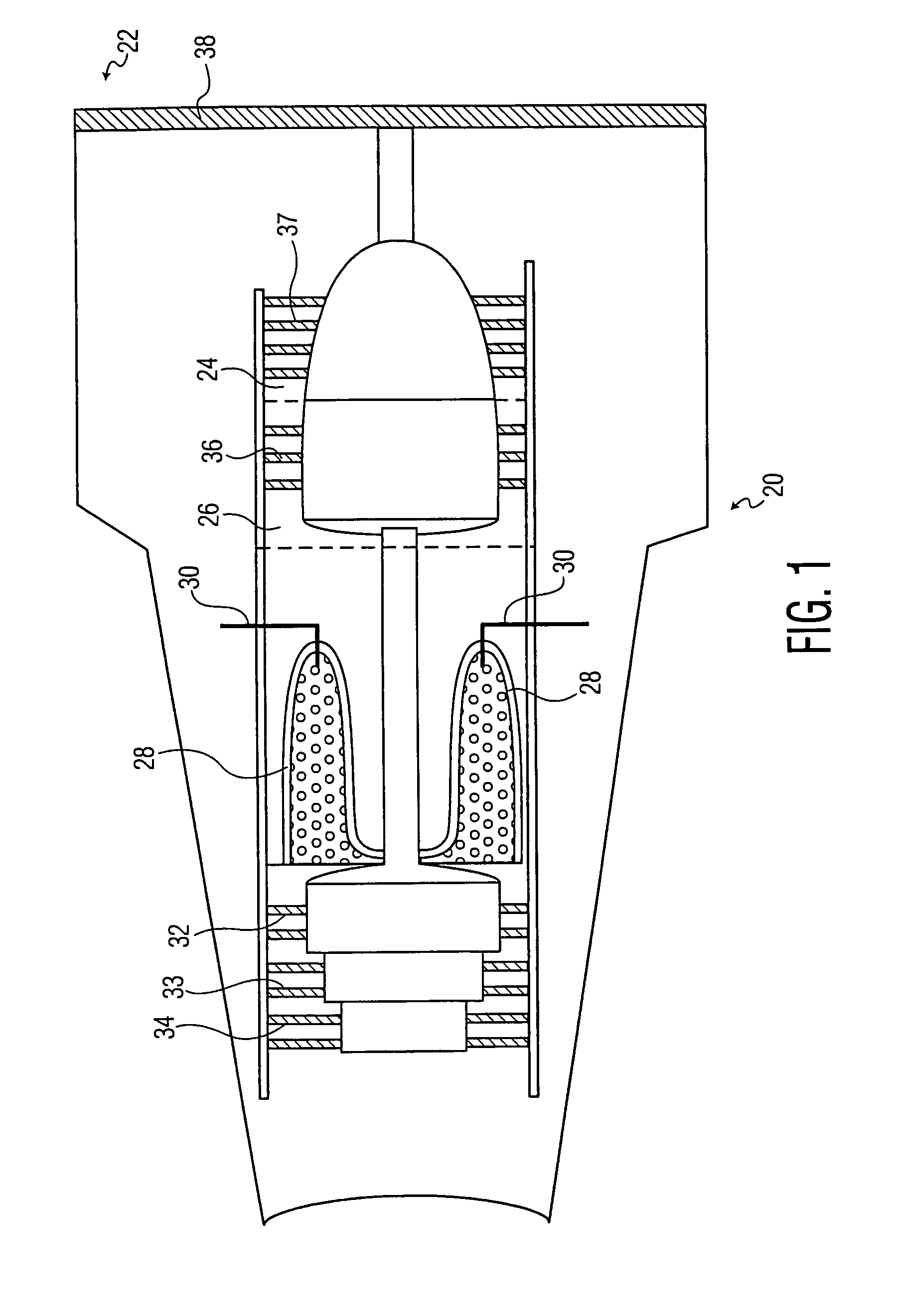
[0049]With reference to the figures for purposes of illustration, the present invention is embodied in a jet engine 20 (FIG. 1). A typical jet engine design suitable for use in commercial aviation is two or three spool, turbo fan which generally includes a low pressure compressor 22 that collects air to improve thrust and feeds a portion of the collected air into an intermediate pressure compressor 24 or booster stages, in the case of a two spool design. Pressurized air from the intermediate (or Booster) pressure chamber 24 is subsequently fed to a high pressure chamber 26 which then feeds the highly pressurized air into the combustion chamber 28. As used throughout this description the term “intermediate chamber” may also refer to “booster chamber.” The pressurized air is then mixed with fuel from fuel injectors 30 in the combustion chamber 28 and ignited. The pressurized and heated air is then fed into a turbine region defined by a series of turbine blades 32–34 that are rotated ...


PUM


Abstract

The present invention relates to a system for detecting aerodynamic instabilities in a jet turbine engine having a pressure transducer mounted in the engine. The pressure transducer, welded to a circuit in signal communication with a controller, is adapted to send measured pressure readings from air in a combustion chamber to the controller. The controller, located in spaced apart relation from the engine, is adapted by software to detect pressure patterns from the pressure signals generated by the transducer that are indicative of a stall or surge. A series of fuel and air valves located with compression and combustion chambers of the engine are in signal communication with the controller. The controller in response to detecting pressure signals indicating a stall or surge is operative to signals in the valves to change the air flow, air angle, fuel flow or speed to reduce the possibility of a stall or surge.

Description

BACKGROUND OF THE INVENTION[0001]1. Field of the Invention[0002]The present invention relates to control of a compressor in a gas turbine engine and, more particularly, to control of a compressor by detecting and compensating for aerodynamic instabilities.[0003]2. Description of the Related Art[0004]With the introduction of the gas turbine engine, the speed and reliability of air travel has improved significantly. The gas turbine engine also known as a turbo-jet engine provides propulsion through the acceleration of a stream of air or gas which is expelled at a high velocity. The typical turbo-jet engine includes three basic functional elements a compressor for gathering and pressurizing the air, a combustor chamber for heating the already pressurized air and a turbine for translating the energy released from the pressurized and heated air into mechanical energy and thrust to propel the aircraft forward. While jet engine technology has advanced one of the safest and fastest growing ...

Claims


Application Information

Patent Timeline
Patent Type & Authority Patents(United States)
IPC IPC(8): F02C9/54
CPCF01D17/08F01D21/003F02C9/28F04D27/001F23N5/16G01M15/14F05D2300/50F23N2041/20Y02T50/672F05D2260/80F05D2270/301F23N2025/04F23N2225/04F23N2241/20Y02T50/60
Inventor KURTZ, ANTHONY D.CHIVERS, JOHNEPSTEIN, ALAN
Owner KULITE SEMICON PRODS
Why Eureka
Try Eureka