Failure diagnosis apparatus for evaporative fuel processing system

a technology of failure diagnosis and evaporative fuel, which is applied in the direction of combustion air/fuel air treatment, electric control, instruments, etc., can solve the problems of increasing the cost of the apparatus, reducing the load current value of the motor pump, and complicating the configuration of the apparatus, so as to achieve the effect of simple configuration

Active Publication Date: 2007-01-09
HONDA MOTOR CO LTD
View PDF6 Cites 16 Cited by
  • Summary
  • Abstract
  • Description
  • Claims
  • Application Information

AI Technical Summary

Benefits of technology

[0006]It is an aspect of the present invention to provide a failure diagnosis apparatus having a relatively simple configuration and which rapidly determines the presence of a leak in the evaporative fuel processing system during stoppage of the internal combustion engine.
[0008]With the above-described configuration, one of a determination result of the first determining means which performs a determination based on a determination parameter corresponding to a second-order derivative value of the detected pressure and a determination result of the second determining means which performs a determination based on the staying time period of the detected pressure, is selected according to the evaporative fuel parameter. The determination by the first determining means is suitable for a condition where a lot of evaporative fuel is generated, while the determination by the second determining means is suitable for a condition where an amount of generated evaporative fuel is little. Therefore, by selecting one of the determination results of the first and second determining means according to the evaporative fuel parameter, accurate determination is performed using a failure diagnosis apparatus having a simple configuration.

Problems solved by technology

Specifically, when a leak is determined to be present in the evaporative fuel processing system, the load current value of the motor pump decreases.
In the conventional failure diagnosis apparatus described above, use of a motor pump is necessary to perform the pressurization, which complicates configuration of the apparatus and increases the cost of the apparatus.
Further, if there is a leak, another problem with the conventional failure diagnosis apparatus is that the evaporative fuel in the evaporative fuel processing system is emitted to the atmosphere by the pressurized air.

Method used


Image

  • Failure diagnosis apparatus for evaporative fuel processing system
  • Failure diagnosis apparatus for evaporative fuel processing system
  • Failure diagnosis apparatus for evaporative fuel processing system

Examples


Embodiment Construction

[0036]Preferred embodiments of the present invention will now be described with reference to the drawings.

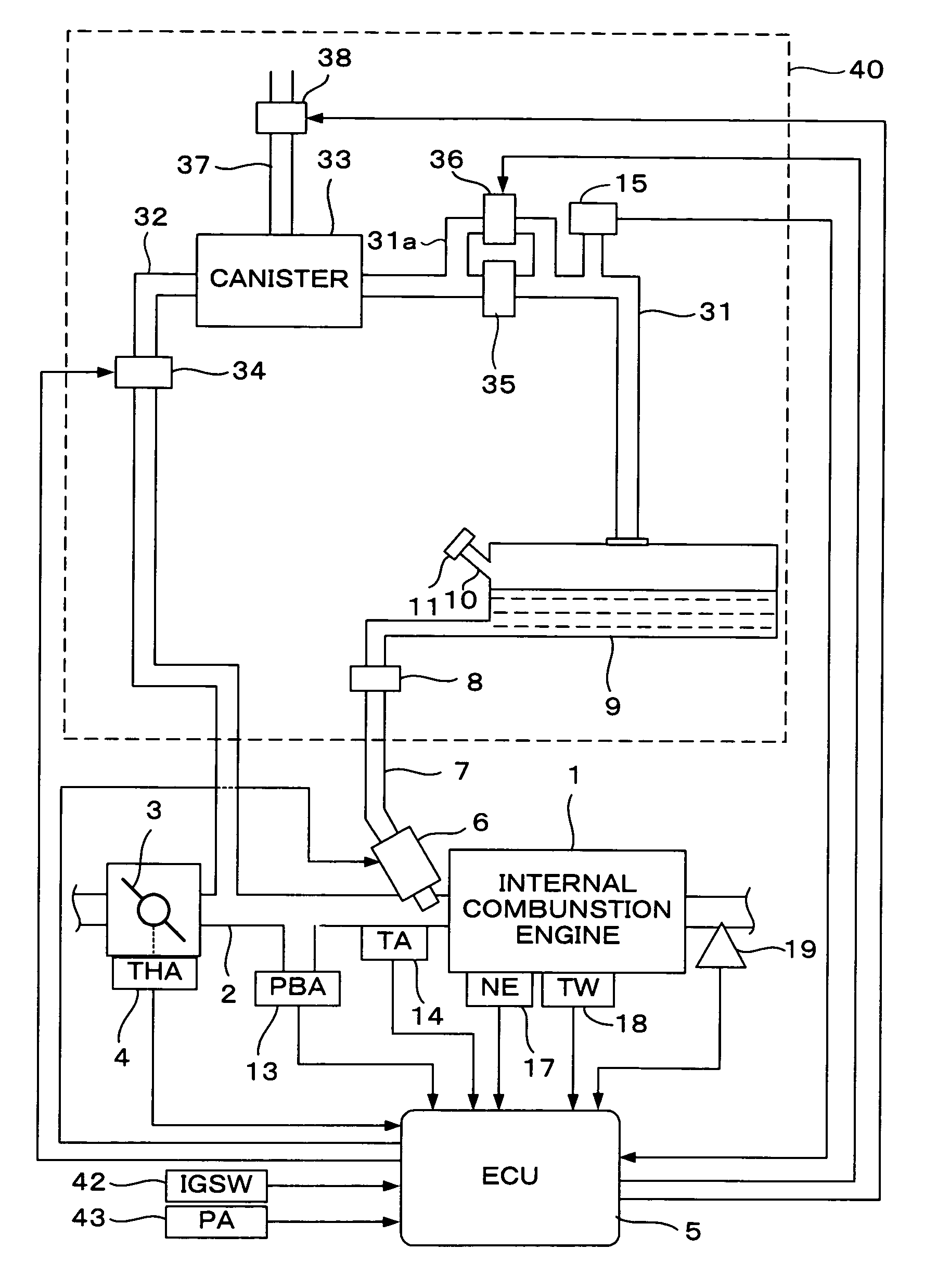
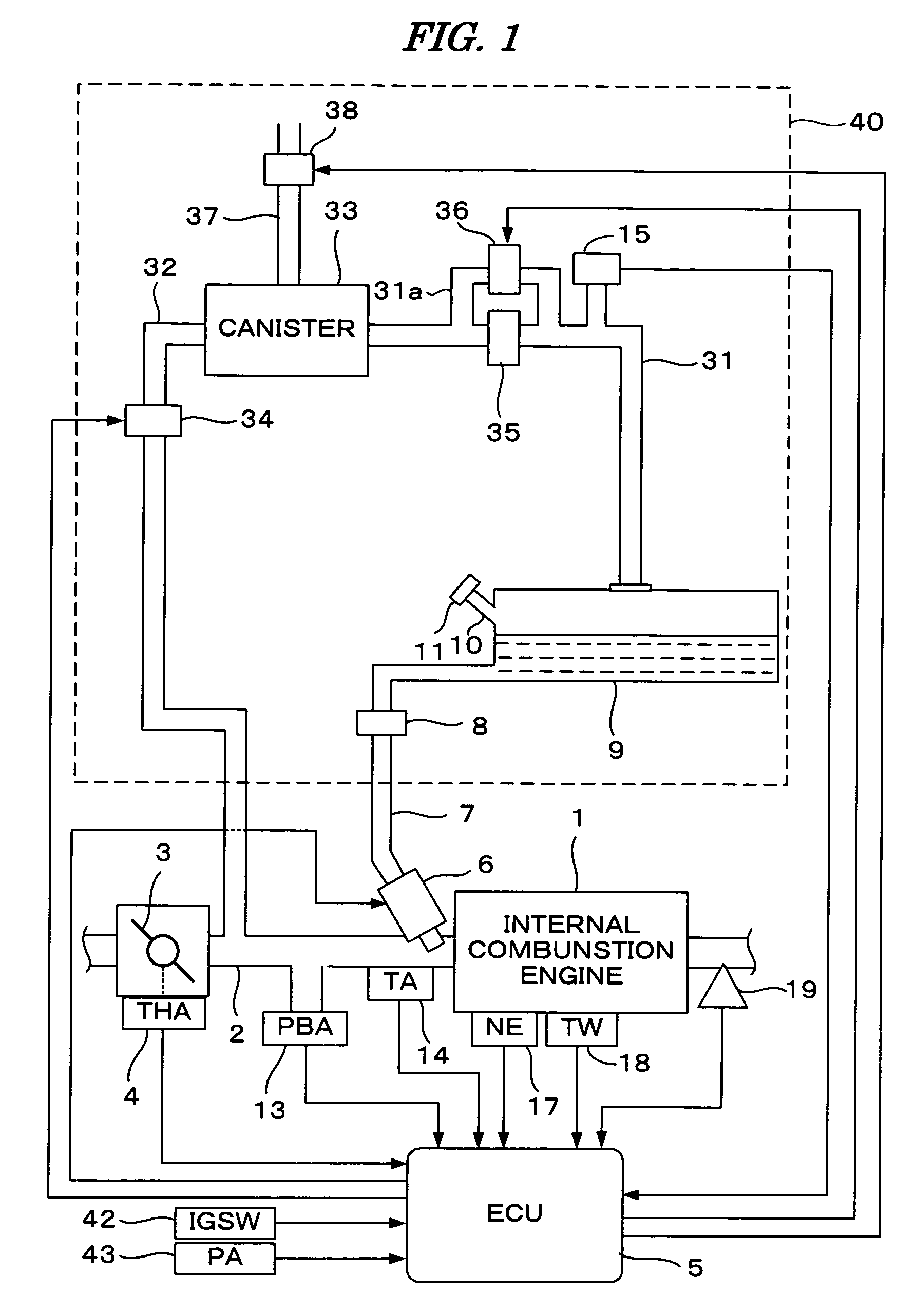
[0037]FIG. 1 is a schematic diagram showing a configuration of an evaporative fuel processing system and a control system for an internal combustion engine according to a first embodiment of the present invention. Referring to FIG. 1, reference numeral 1 denotes an internal combustion engine (hereinafter referred to as “engine”) having a plurality of (e.g., four) cylinders. The engine 1 is provided with an intake pipe 2 in which a throttle valve 3 is mounted. A throttle valve opening (THA) sensor 4 is connected to the throttle valve 3. The throttle valve opening sensor 4 outputs an electrical signal corresponding to an opening of the throttle valve 3 and supplies the electrical signal to an electronic control unit (hereinafter referred to as “ECU”) 5.

[0038]A portion of the intake pipe 2, between the engine 1 and the throttle valve 3, is provided with a plurality of fuel injectio...


PUM


Abstract

A failure diagnosis apparatus for diagnosing a failure of an evaporative fuel processing system wherein a pressure in the evaporative fuel processing system is detected, and a purge control valve and a vent shut valve are closed when stoppage of the engine is detected. A determination is made as to whether there is a leak in the evaporative fuel processing system based on the detected pressure during a predetermined determination period after closing of the purge control and vent shut valves. The determination result is decided according to a parameter indicative of an amount of evaporative fuel generated in the fuel tank after stoppage of the engine.

Description

BACKGROUND OF THE INVENTION[0001]1. Field of the Invention[0002]The present invention relates to a failure diagnosis apparatus for diagnosing failure of an evaporative fuel processing system which temporarily stores evaporative fuel generated in a fuel tank and supplies the stored evaporative fuel to an internal combustion engine.[0003]2. Description of the Related Art[0004]A failure diagnosis apparatus which determines whether there is a leak in an evaporative fuel processing system after stoppage of the internal combustion engine is disclosed, for example, in Japanese Patent Laid-open No. 2002-357164. According to the conventional failure diagnosis apparatus, air is pressurized by a motor pump and introduced into the evaporative fuel processing system, and a determination is made based on a value of the load current of the motor pump as to whether there is a leak in the evaporative fuel processing system. Specifically, when a leak is determined to be present in the evaporative fue...

Claims


Application Information

Patent Timeline
Patent Type & Authority Patents(United States)
IPC IPC(8): F02M37/04F02M33/02
CPCF02M25/0827F02M25/0809F02M25/08F02D45/00
Inventor SHIKAMA, MAHITOSATO, DAISUKEHARA, TAKESHIYAMAGUCHI, TAKASHIYOSHIKI, KOICHI
Owner HONDA MOTOR CO LTD
Why Eureka
Try Eureka