Progressive refractive power lens

a technology of power lens and lens thickness, applied in the field of progressive power spectacle lens, can solve the problems of inferior lens thickness and appearance, power lens may have a sense of incongruity, and the surface having a radius of curvature larger than 1.5 m cannot be processed, and achieve the effect of low cost manufacturing

Active Publication Date: 2007-01-09
HOYA LENS MFG PHILIPPINES
View PDF5 Cites 71 Cited by
  • Summary
  • Abstract
  • Description
  • Claims
  • Application Information

AI Technical Summary

Benefits of technology

[0012]For providing a progressive-power lens which is made thin and manufactured at low cost while maintaining optical characteristics of-an inside surface progressive-power lens, a progressive-power lens according to the present invention comprises a distance portion, a near portion and an intermediate portion, wherein an object-side refractive surface is formed from a part of an aspherical surface symmetric with respect to a rotational axis and an eyeball-side refractive surface is from a progressive surface. The progressive-power lens is characterized in that there is a relationship shown below between a curvature C1 at a distance reference point of the object-side refractive surface and a curvature C2 at a near reference point of the object-side refractive surface:C1<C2

Problems solved by technology

There are also a pair of aberration portions, which are not suitable for optical use, with the intermediate and the near portions on their sides interposed between the aberration regions.
These aberration regions produced by smoothly connecting the power difference between the distance and near portions inevitably exist in a progressive-power lens as its drawback.
Thus, some people who use the progressive-power lens for the first time or who have replaced a differently designed progressive-power lens with the outside surface progressive-power lens may have a sense of incongruity.
This is undesirable in view of manufacture, since a curved surface having a concave at the distance portion and a convex at the near portion requires a more complicated processing technique than the curved surface having concaves at both distance and near portions.
For example, a surface having a radius of curvature larger than 1.5 m cannot be processed due to the restriction of a processing machine.
Conversely, the inside surface progressive-power lens is superior in view of optical characteristics such as less distortion, but is inferior in lens thickness and appearance.
However, the both-surface progressive-power lens involves a higher manufacturing cost due to its complicated processes and longer processing time since the progressive surface is formed from freely curved surfaces having complicated configurations.

Method used


Image

  • Progressive refractive power lens
  • Progressive refractive power lens
  • Progressive refractive power lens

Examples


first embodiment

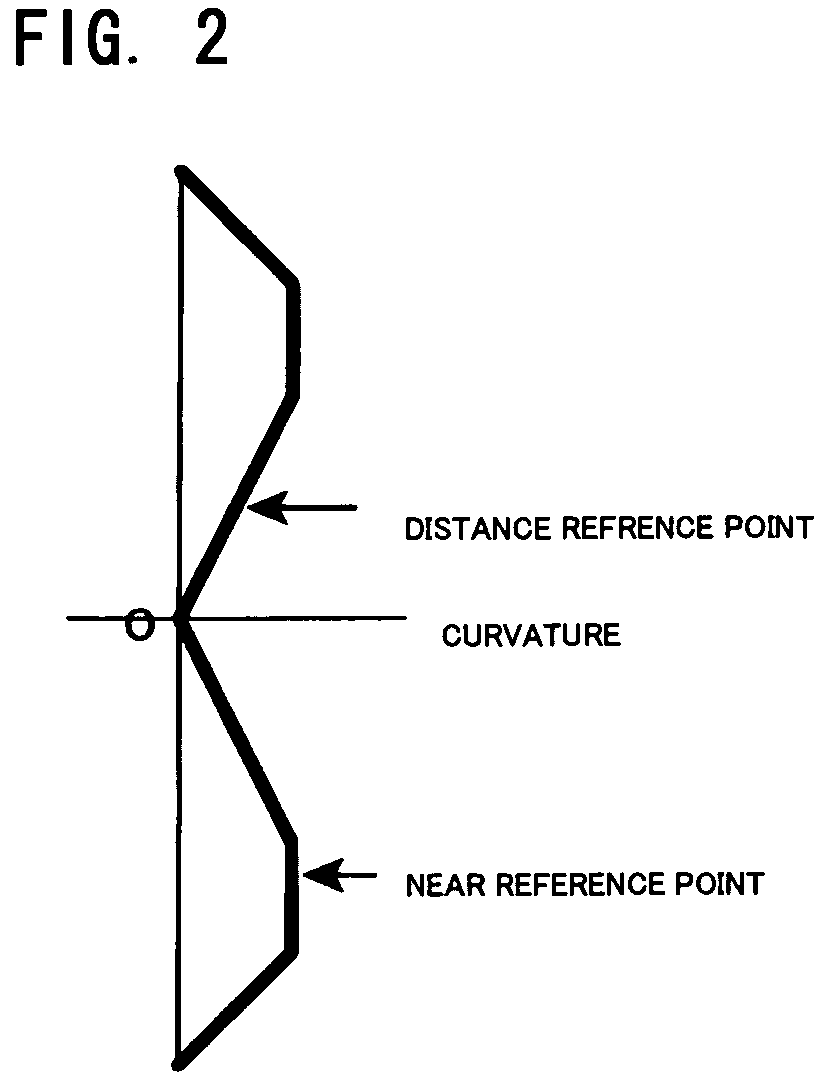
[0038]The present invention is now described in more detail. FIG. 2 shows curvature variation of an object-side refractive surface in a In this embodiment, an axis passing a geometrical center O of the lens corresponds to a symmetric axis for rotation. In the figure, the lateral axis indicates values of curvature, while the longitudinal axis indicates distance from the center of the lens. Thus, the upper portion in the figure shows the distance portion, whereas the lower portion shows the near and intermediate portions. The curvature variations are vertically symmetric with respect to the center O. The curvature at the distance reference point is smaller than that at the near reference point. For example, for manufacturing a lens having a distance power of 3.00 D and an addition power of 3.00 D, the surface power at the near portion of the eye-ball side refractive surface is set at the processing limit value of 0.45 D. As the lens having the distance power of 3.00 D and the additio...

second embodiment

[0040]FIG. 3 illustrates curvature variation of an object-side refractive surface in a In this embodiment, constant curvatures are obtained in a range of 5 mm in diameter from the centers set at the distance and near reference points. The distance and near reference points correspond to the points at which the power is measured for examining lens specifications by means of a lens meter or other apparatus. Since the lens meter generally makes a measurement at the minimum aperture of 5 mm in diameter, a stable measurement of power can be taken by reducing the variations in curvature in this range. From the study of the writer of this description, the tolerance of the power sometimes exceeds the standard values specified in Japanese Industrial Standard and International Organization for Standardization when the curvature varies through 0.25 D in this range. Thus, it is desirable to confine the variations of the surface power within 0.25 D in the range of 5 mm in diameter from the cent...

third embodiment

[0041]FIG. 4 illustrates curvature variation in a In this embodiment, monotonous increase in curvature from the rotational center till the outer periphery can be observed, providing lower improvement in lens thickness compared with the above-described embodiments. However, a highly simplified configuration of an object-side refractive surface allows the manufacturing cost to be reduced considerably.


PUM


Abstract

It has been difficult to manufacture an inside surface progressive-power lens which is as thin as an outside surface progressive-power lens due to a limited configuration of an object-side refractive surface of the inside surface progressive-power lens. However, a thin progressive-power lens with less blur and distortion can be provided at a reduced cost by forming its object-side refractive surface from an aspherical surface which is symmetric with respect to a rotational axis and has a smaller curvature at a distance reference point than that at a near reference point, and by forming an eyeball-side refractive surface from a combination of a progressive surface, an astigmatic refraction surface and an “as-worn” corrective aspherical surface.

Description

TECHNICAL FIELD[0001]A progressive-power lens of the present invention pertains to a progressive-power spectacle lens chiefly for a person having poor accomoddation.BACKGROUND ART[0002]A basic structure of a progressive-power lens is first described with reference to FIG. 8. The progressive-power lens comprises a distance portion having refracting power (power) for distant view, a near portion having power for near view, and an intermediate portion which is disposed between the distance and near portions and progressively varies its power. The power difference between the distance portion and the near portion is known as addition power, which is set at an appropriate value according to the level of accommodation of a wearer of glasses. There are also a pair of aberration portions, which are not suitable for optical use, with the intermediate and the near portions on their sides interposed between the aberration regions. These aberration regions produced by smoothly connecting the po...

Claims


Application Information

Patent Timeline
Patent Type & Authority Patents(United States)
IPC IPC(8): G02C7/06G02C7/10G02C7/02
CPCG02C7/068G02C7/061G02C7/06
Inventor KATO, KAZUTOSHI
Owner HOYA LENS MFG PHILIPPINES
Why Eureka
Try Eureka