Blade of a turbine

a turbine blade and turbine blade technology, applied in the direction of propulsive elements, vessel construction, marine propulsion, etc., can solve the problems of blade material cracks, blades in fluid-flow machines are often subject to considerable mechanical loads, and the radius of curvature of the surface defining the slot at the end is reduced, and the stress occurring in particular at such curvature is reduced.

Inactive Publication Date: 2007-01-09
SIEMENS AG
View PDF11 Cites 14 Cited by
  • Summary
  • Abstract
  • Description
  • Claims
  • Application Information

AI Technical Summary

Benefits of technology

[0017]The relief slot preferably has an approximately circular widened portion at its end opposite the blade trailing edge. Due to such a circular widened portion, the radii of curvature of the surfaces defining the slot at the end are reduced and thus the stresses occurring in particular at such curvatures are reduced. In particular, the circular widened portion is a circular hole, from which the slot extends through the blade trailing edge. The slot is preferably cut by means of a laser beam or it is milled.
[0018]The measures described above for the relief of thermal stresses in the blade trailing edge are also equally suitable for reducing stresses in the rounded portion between the blade trailing edge and the root region.

Problems solved by technology

Such blades in fluid-flow machines are often subjected to considerable mechanical loads.
As a result, cracks may form in the blade material, and these cracks propagate in the course of time when stress is continuous.
Finally, failure of the blade may occur, the blade breaking into pieces or fragments being released.
For blades following in the direction of flow, this may lead to considerable damage.
Depending on the speed of the processes, a significant reduction in the availability of the turbine may occur as a result, since regular service intervals lead to turbine downtimes.

Method used


Image

  • Blade of a turbine
  • Blade of a turbine
  • Blade of a turbine

Examples


Embodiment Construction

[0025]The same reference numerals have the same meaning in the various figures.

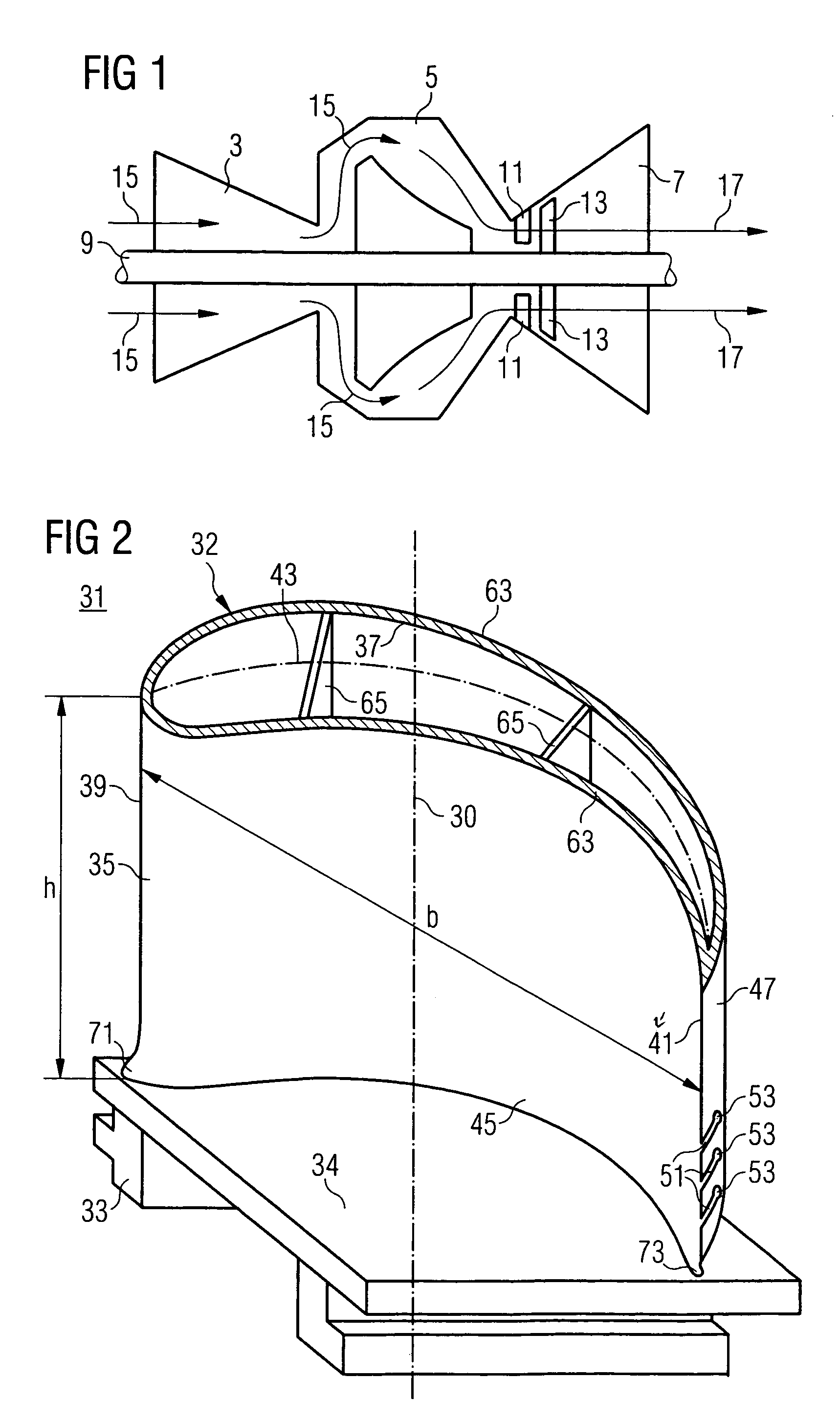
[0026]FIG. 1 shows a gas turbine 1. The gas turbine 1 is directed along a turbine axis 10 and has, following one another along the turbine axis 10, a compressor 3, a combustion chamber 5 and a turbine part 7. The compressor 3 and the turbine part 7 are arranged on a common turbine shaft 9. Formed in the turbine part 7 is a hot-gas duct 12, into which guide blades 11 and moving blades 13, which are arranged on the turbine shaft 9, project.

[0027]During operation of the gas turbine 1, ambient air is drawn in by the compressor 3 and compressed to form compressor air 15. The compressor air 15 is burned with fuel in the combustion chamber 5 to form hot gas 17, which flows through the hot-gas duct 12. In the process, the turbine shaft 9 is set in motion via the effect on the moving blades 13. The rotational energy of the turbine shaft 9 can be used, for example, for generating electrical energy.

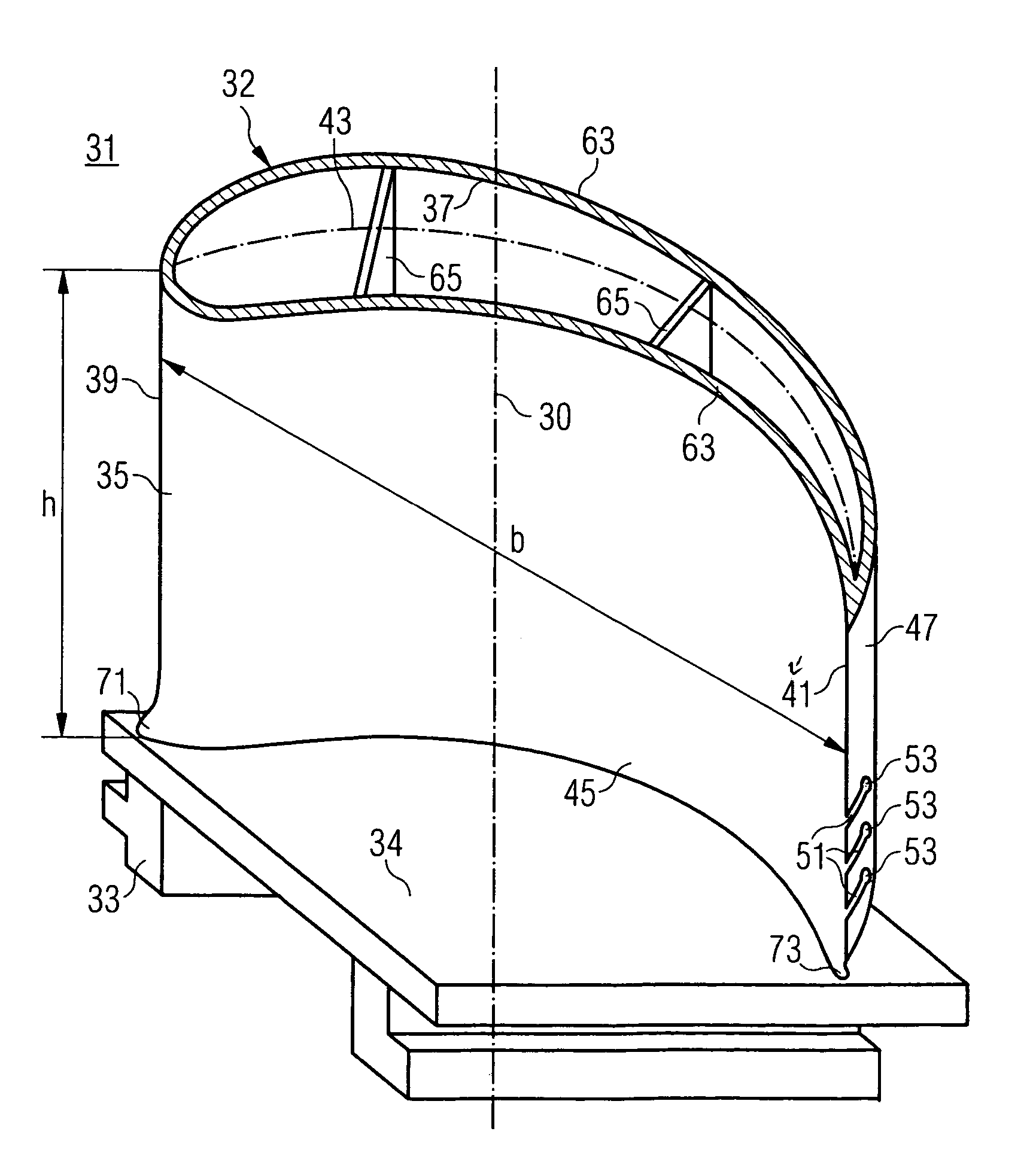
[0028]FIG. 2 show...


PUM


Abstract

The invention relates to a turbine blade (31) having a root region (33), a tip region (37) and a blade airfoil (35), a rounded portion (73) being formed between the root region (33) and the blade airfoil (35), and relief slots (51) passing through the blade trailing edge (41) in the region of this rounded portion (73), thermal expansions being compensated for and thus thermal stresses being minimized by these relief slots (51).

Description

CROSS REFERENCE TO RELATED APPLICATION[0001]This application claims priority of the European application No. 03020211.3 EP filed Sep. 5, 2003, which is incorporated by reference herein in its entirety.FIELD OF THE INVENTION[0002]The invention relates to the blade of a turbine, which blade is directed along a blade axis, is formed from a basic body and comprises a root region, a tip region and a blade airfoil having an airfoil height extending from the root region to the tip region. The invention also relates to a method of preventing the propagation of cracks in the blade airfoil of the blade of a turbine.BACKGROUND OF THE INVENTION[0003]In turbines, a flow medium is transported in a flow duct in order to obtain energy therefrom. To this end, turbine blades are arranged in the flow duct. For example, in the flow duct of an axial gas turbine, guide-blade rings formed from guide blades and moving-blade rings formed from moving blades are arranged alternately following one another in t...

Claims


Application Information

Patent Timeline
Patent Type & Authority Patents(United States)
IPC IPC(8): F04D29/32F01D5/14
CPCF01D5/147F01D5/143
Inventor AHMAD, FATHI
Owner SIEMENS AG
Why Eureka
Try Eureka