Radial-capitellar implant

a technology of radial capitellar and joint replacement, which is applied in the field of joint replacement prostheses for the human elbow, can solve the problems of forearm, affecting the function of the elbow, and damage to the head of the radius, so as to improve the wear characteristics, and reduce the effect of radial head damag

Active Publication Date: 2007-01-09
MAYO FOUND FOR MEDICAL EDUCATION & RES
View PDF55 Cites 54 Cited by
  • Summary
  • Abstract
  • Description
  • Claims
  • Application Information

AI Technical Summary

Benefits of technology

[0015]The capitellar implant of the present invention generally includes a body and a stem. The body of the capitellar implant defines a convex articular face. The convex articular face may have a spherical surface and extends about one hundred thirty five to one hundred forty degrees. The capitellar implant further includes a flat on its medial side and a curved flat on its lateral side. The curved flat on the lateral surface allows for excursion of the radial nerve over the lateral surface of the implant. The curved flat also facilitates the smooth gliding of the joint capsule and ligamentous structures over the implant during flexion / extension and pronosupinatory motions. The convex articular face allows articulation of the capitellar implant with the head of the radius over an arc of approximately one hundred thirty five to one hundred forty degrees to allow full range of motion in flexion and extension of the forearm.
[0022]The stem of this embodiment includes a stem with a collar similar to that described above as well as a spheroidal ball protruding from the stem and extending from the collar in a direction opposite the stem. The spheroidal protrusion rests in a spheroidal female cavity. The female cavity accepts the male portion of the ball joint of the head portion and the spheroidal protrusion inserts into the female ball and socket portion of the head of the radial head implant. This structure increases the contact area between the articular head and the articular stem improving the wear characteristics and distributing loading over a larger area. In this embodiment of the invention the stem may also be treated to encourage osseointegration such as by application of a commercially pure titanium plasma coating.

Problems solved by technology

The radial head can be damaged in many ways.
One common source of damage the head of the radius is a fall onto an outstretched hand.
Unfortunately, radial head resection tends to cause significant adverse effects on elbow and forearm function.
Resection of the radial head tends to cause persistent elbow instability following elbow fracture, dislocation, rotational instability injuries and medial lateral translation injuries.
Excision of the radial head can also cause forearm axial instability, particularly if the remaining stabilizing structures have been compromised.
Since the radial head acts as a secondary stabilizer to the elbow joint, once the radial head is removed the soft tissue stabilizers including the collateral ligaments, the interosseous membrane and the articular surfaces of the radial ulnar joints may be compromised and the instability of the joint tends to increase.
This allows the use of a radial head implant in situations where the radial head may be damaged in such a way as to make implantation of a fixed radial head implant difficult or impossible.
Unfortunately, some falls onto an outstretched hand will also damage the capitellum of the humerus.
In addition, the capitellum is sometimes to subject to arthritic degeneration or increased wear after placement of a radial head implant.
Resection of the radial head leaves the patient with a so-called ulna plus variation which tends to lead to wrist pain which, in turn, can be debilitating.
In the case of an Essex-Lopresti lesion or interosseous ligament tear, the transfer of loads from the hand and then from the radius to the ulna is compromised.
This lack of transfer from the radius to the ulna creates an increased load at the radial head where it meets the capitellum which increases wear on the capitellum as well as the radial head.

Method used


Image

  • Radial-capitellar implant
  • Radial-capitellar implant
  • Radial-capitellar implant

Examples


Embodiment Construction

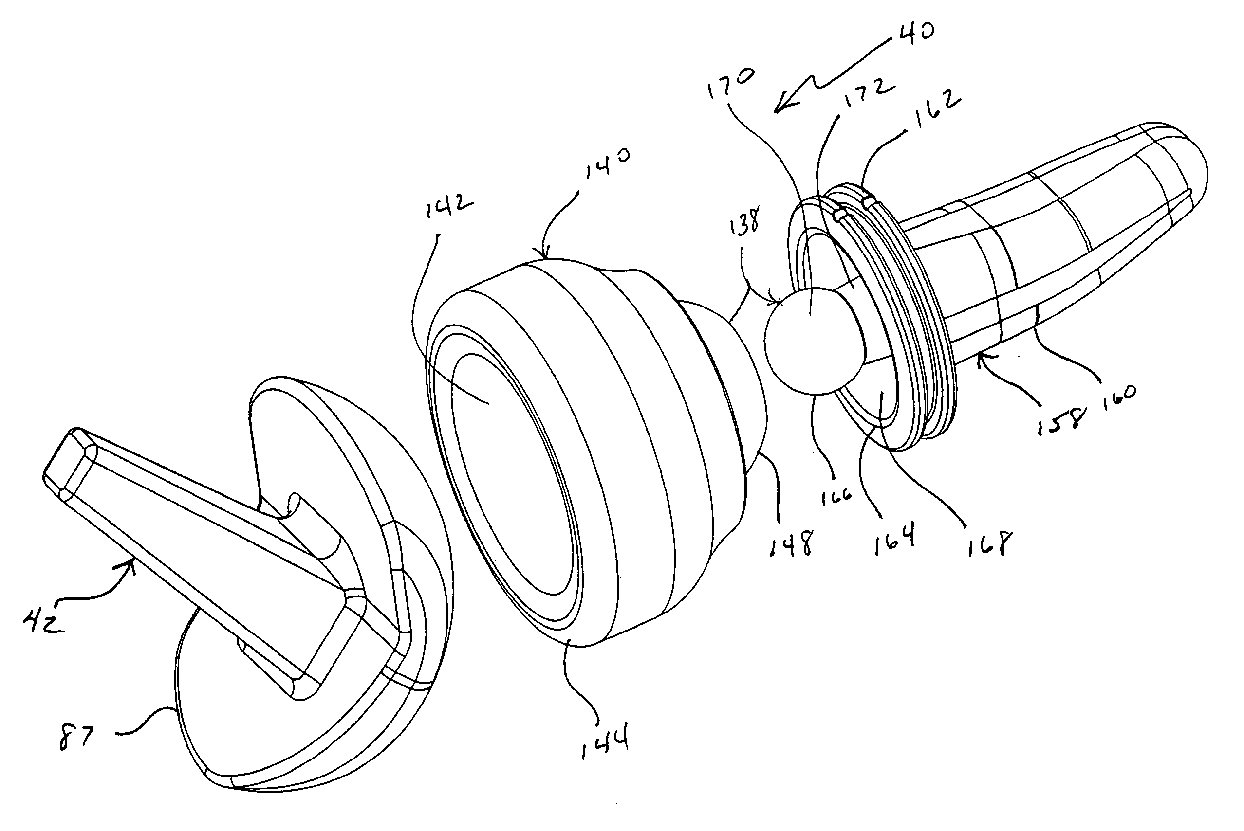
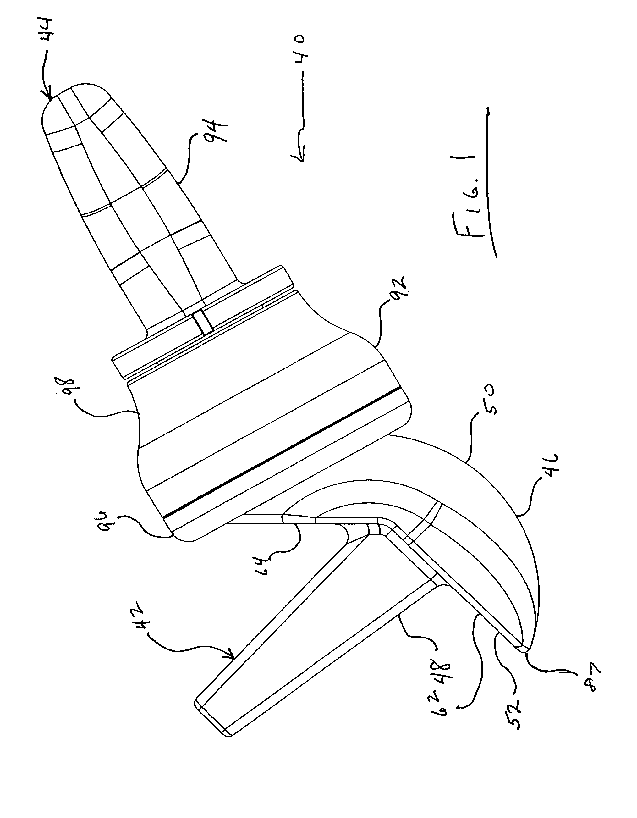
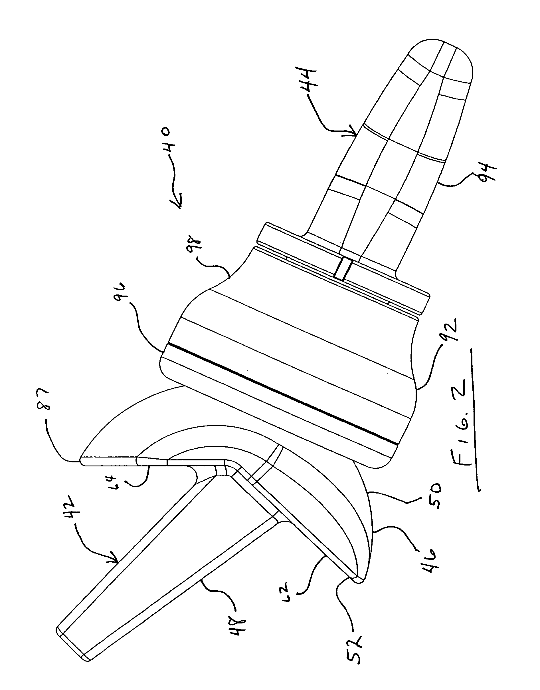
[0059]The radial-capitellar implant 40 of the present invention generally includes capitellar prosthesis 42 and radial prosthesis 44. Referring initially to FIGS. 1–5 capitellar prosthesis 42 and radial prosthesis 44 are shown in various views as articulated with one another in various degrees of flexion and extension.

[0060]Referring particularly to FIGS. 1–6 and 11–16 capitellar prosthesis 42 generally includes body 46 and stem 48. Stem 48 is joined to body 46 extending outwardly from bone interface surface 52 of body 46. Articular face 50 presents a substantially spheroidal surface. Body 46 and stem 48 may be integrally formed from a single piece of material such as by casting or machining.

[0061]Articular face 50 is smooth and may be mirror polished to facilitate smooth articulation. Articular face 50 may present a substantially spheroidal convex surface

[0062]Articular face 50 extends over an arc of approximately 170 to 190 degrees in a first direction and an arc of 80 to 100 degr...


PUM

PropertyMeasurementUnit
lateral angleaaaaaaaaaa
angleaaaaaaaaaa
obtuse angleaaaaaaaaaa

Abstract

A radial-capitellar implant for surgical replacement of the capitellum of the humerus and, optionally, the head of the radius. The radial-capitellar implant includes a capitellar implant or surface replacement arthroplasty of the capitellum and a radial prosthesis for replacement of the head of the radius. In one embodiment the radial prosthesis includes an articular head which moveable articulates with a stem implantable in the radius.

Description

FIELD OF THE INVENTION[0001]The invention relates generally to the field of joint replacement prostheses for the human body. More specifically, the invention relates to joint replacement prostheses for the human elbow.BACKGROUND OF THE INVENTION[0002]The elbow is formed at the meeting of the distal end of the humerus and the proximal ends of the radius and ulna. In the elbow, the head of radius articulates with the capitellum of the humerus and radial notch of the ulna. The trochlear notch of the ulna articulates with the trochlea of the humerus. When the forearm is in extreme flexion, the head of the radius fits into the radial fossa located just above the capitellum. The lateral epicondyle is found on the lateral aspect of the humerus just above the capitellum. The lateral epicondyle serves as the insertion for one portion of the supinator muscle which attaches at about the proximal third of the radius.[0003]Along their lengths the radius and ulna are joined by the interosseous li...

Claims


Application Information

Patent Timeline
Patent Type & Authority Patents(United States)
IPC IPC(8): A61F2/38
CPCA61F2/3804A61F2/30767A61F2310/00952A61F2002/30153A61F2002/30332A61F2002/30354A61F2002/30574A61F2002/30604A61F2002/30662A61F2002/30663A61F2002/30878A61F2002/3809A61F2002/3822A61F2002/3827A61F2220/0033A61F2230/0019A61F2310/00017A61F2310/00023A61F2310/00029A61F2310/00407A61F2002/30782A61F2002/30894
Inventor COONEY, III, WILLIAM P.MORREY, BERNARD F.LEIBEL, DAVID A.
Owner MAYO FOUND FOR MEDICAL EDUCATION & RES
Why Eureka
Try Eureka