Trip-free PCB mountable relay configuration and method

a relay and pcb technology, applied in relays, circuit-breaking switches, printed circuit non-printed electric components associations, etc., can solve the problems of unrealized expected cost savings from parts count reduction, disconnect between parts count and cost, and overheating, etc., to simplify the task of meeting manufacturing tolerances, reduce overall housing dimensions, and reduce overall relay costs

Active Publication Date: 2007-01-09
ROCKWELL AUTOMATION TECH
View PDF24 Cites 17 Cited by
  • Summary
  • Abstract
  • Description
  • Claims
  • Application Information

AI Technical Summary

Benefits of technology

[0013]It has been recognized that the PCB associated with a mechanical trip free relay configuration can be placed outside a relay housing thereby reducing overall housing dimensions. Reduced housing dimensions simplify the task of meeting manufacturing tolerances and therefore reduce overall relay costs despite, in at least some cases, increasing overall parts count. Also, in this regard, in at least some cases, it is believed that reduced dimensions will lead to even more accurate cost effective tolerance capabilities and hence better working and new trip free mechanisms not thought possible prior to this concept.
[0014]It has also been recognized that, where all mechanical trip free relay components are placed within a single housing and the associated PCB is placed outside the relay housing, it is advantageous in at least some embodiments to provide PCB linkable pins that extend from the relay housing and that are suitable for linkage to the associated PCB. In at least some embodiments the PCB pins extend form one side of the housing and are arranged in a predefined pattern that matches a pattern of linkages on the associated PCB to facilitate easy linkage.

Problems solved by technology

Overload relays are electrical switches typically employed in industry to protect equipment from excessive current conditions that in turn cause overheating, performance degradation and eventually equipment malfunction or destruction.
Unfortunately, while the single housing approach to trip free relay design generally reduces parts count, expected cost savings from parts count reduction has never been realized.
The disconnect between parts count and cost is in great part due to increased manufacturing difficulties attributable to the single housing designs.
To this end, while the size of a typical single housing assembly is generally increased to accommodate all of the required trip free relay components, tolerances between housing structure for mounting components have not been commensurately increased.
Thus, more complex manufacturing techniques required to manufacture single housing trip free relays have generally increased relay costs more than the reduction in parts count has reduced costs.

Method used


Image

  • Trip-free PCB mountable relay configuration and method
  • Trip-free PCB mountable relay configuration and method
  • Trip-free PCB mountable relay configuration and method

Examples


Embodiment Construction

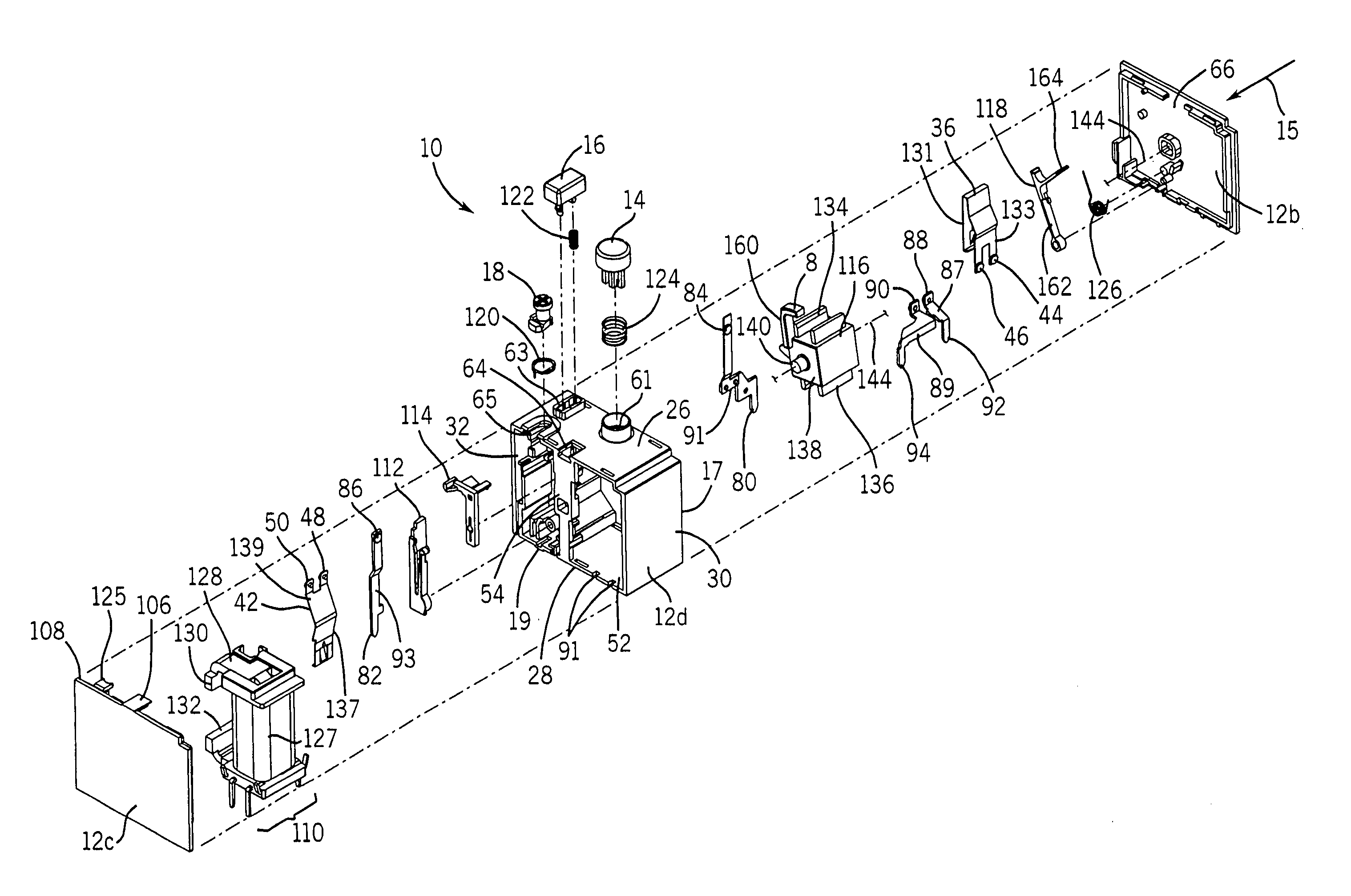
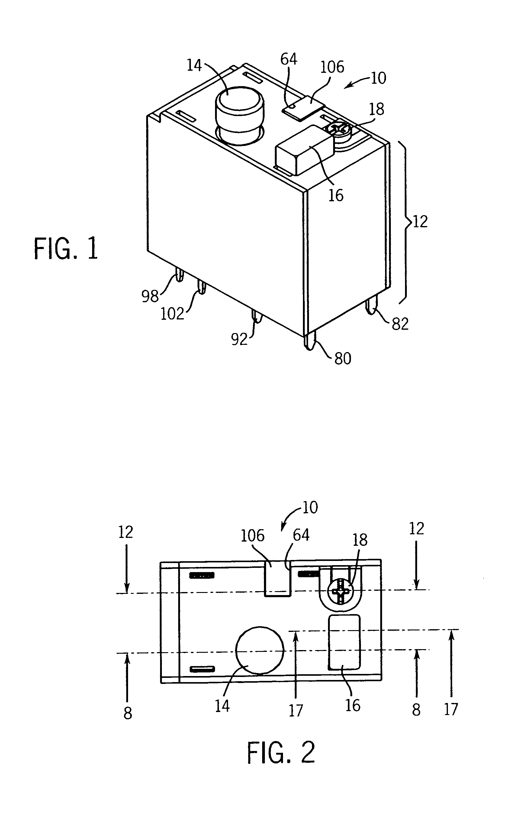
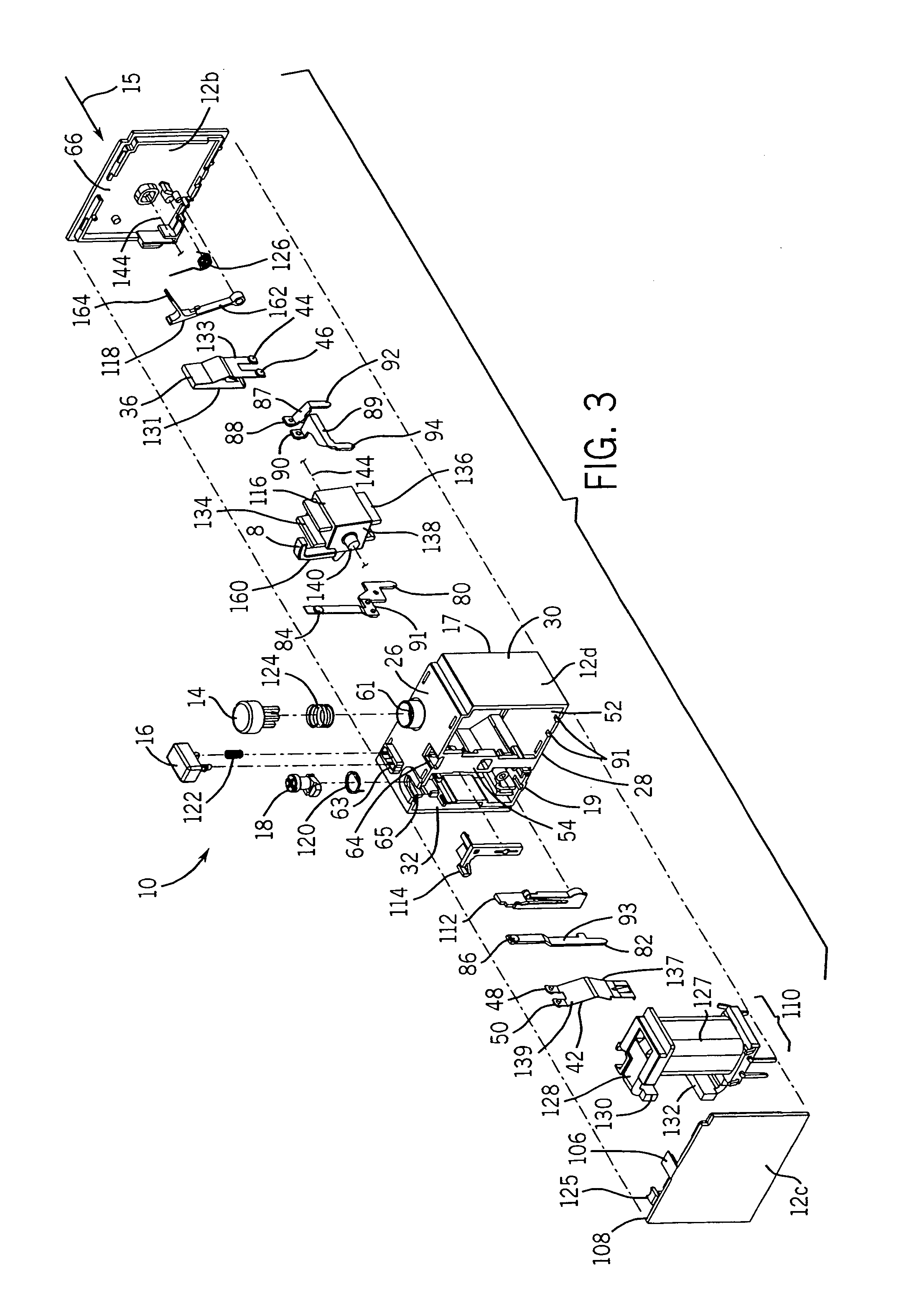
[0050]Referring now to the drawings wherein like reference numerals and labels correspond to similar elements throughout several views and, more specific, referring to FIG. 1, the present invention will be described in the context of exemplary trip-free relay configuration 10. Configuration 10 includes a plurality of components that are housed within a relay housing generally identified by numeral 12 that are linkable to other electronic circuitry (e.g., a printed circuit board (PCB)) via a plurality of electrically conductive pins or terminals extending from an underside of housing 12.

[0051]Generally, the pins include first, second, third and fourth pairs where each first pair pin is integrally connected to a separate normally open contact, each second pair pin is integrally connected to a separate normally closed contact and the third and fourth pin pairs are used to change the states (e.g., open or closed) of the relay contacts. For example, when current flows from the first pin ...


PUM


Abstract

A method and assembly for use with a printed circuit board (PCB), the assembly comprising a relay assembly including a relay housing and a trip free reset assembly mounted within the housing and linked to other relay components mounted within the housing for manually resetting the relay after the relay is tripped and at least one pin linked to at least one of the relay components and including a distal end extending from the housing and suitable for direct connection to the PCB.

Description

CROSS-REFERENCE TO RELATED APPLICATIONS[0001]Not applicable.STATEMENT REGARDING FEDERALLY SPONSORED RESEARCH OR DEVELOPMENT[0002]Not applicable.BACKGROUND OF THE INVENTION[0003]The present invention relates to electrical relays and more specifically to a modular trip free relay suitable for direct connection to a printed circuit board.[0004]Overload relays are electrical switches typically employed in industry to protect equipment from excessive current conditions that in turn cause overheating, performance degradation and eventually equipment malfunction or destruction. For instance, a three phase induction motor is often linked to a power source through a relay commonly referred to as a contactor. A typical contactor includes a separate power path for each of the three motor phases. Contactor motion is typically provided magnetically as the result of power flow through a coil where the current though the coil is controlled by a control switch.[0005]In many cases an overload relay ...

Claims


Application Information

Patent Timeline
Patent Type & Authority Patents(United States)
IPC IPC(8): H01H9/02H01H13/04H01H1/58H01H51/22H01H71/68H01H73/44H05K1/18
CPCH01H51/2227H01H73/44H01H71/68H01H1/5805H05K1/18
Inventor BERGH, DALLAS J.HAENSGEN, STEVEN T.LEHMAN, GARY
Owner ROCKWELL AUTOMATION TECH
Why Eureka
Try Eureka