
Uniformity control using multiple fixed wafer orientations and variable scan velocity

a technology of uniformity control and fixed wafer orientation, applied in the field of uniformity control of ion implantation dose, can solve the problems of difficult to maintain constant tilt and wafer orientation, complicate the mechanism, and introduce unnecessary complexity into achieving uniform dose, so as to enhance dose uniformity during ion implantation

Active Publication Date: 2007-01-09
VARIAN SEMICON EQUIP ASSOC INC
View PDF3 Cites 7 Cited by
  • Summary
  • Abstract
  • Description
  • Claims
  • Application Information

AI Technical Summary

Benefits of technology

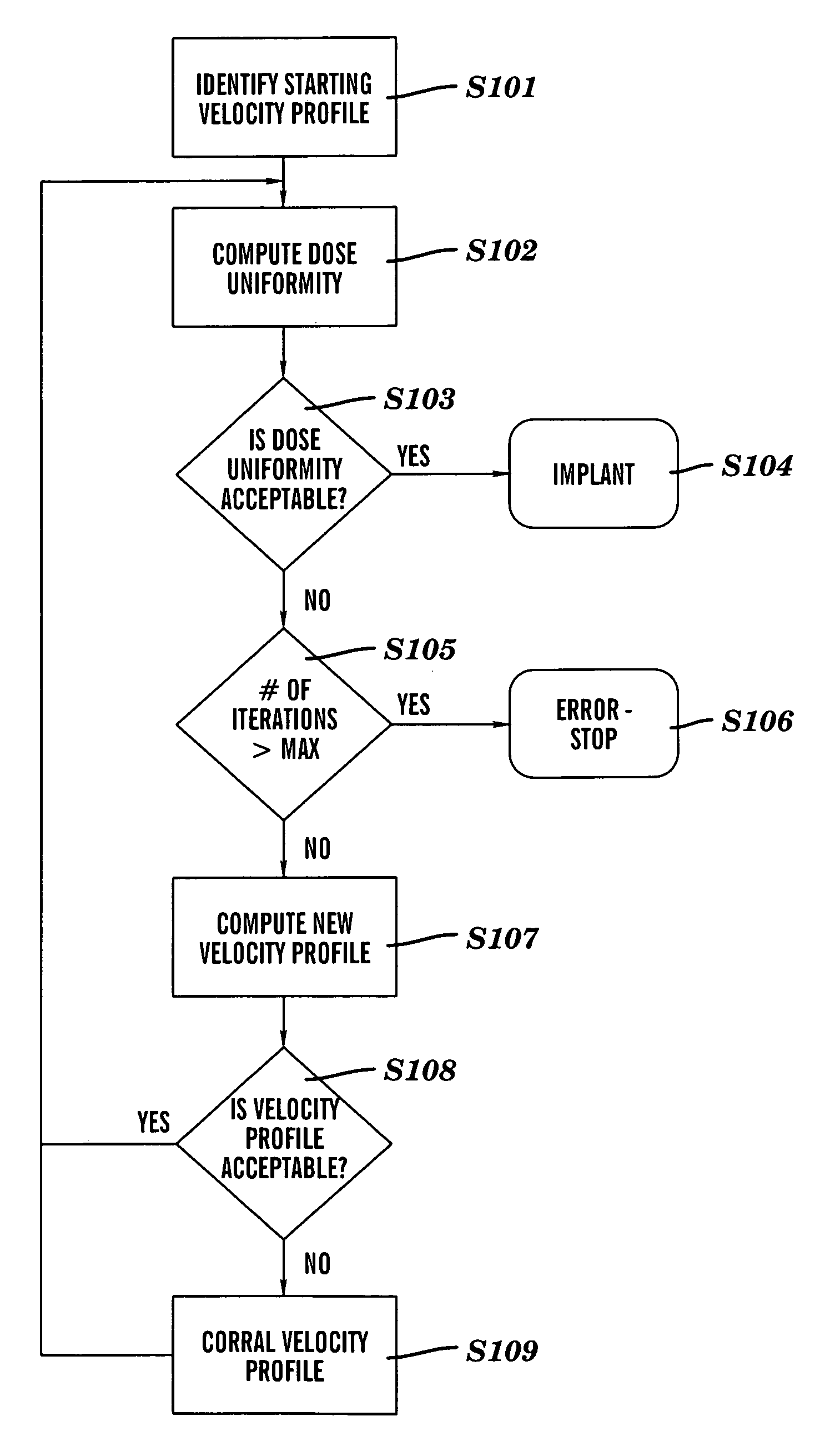
The invention is a system, method, and program product for improving the uniformity of ion implantation during semiconductor device fabrication. It involves using an at least partially un-tuned ion beam and scanning it in multiple orientations at variable scan velocities dictated by an ion beam profile. The non-uniform scan velocities are dictated by a scan velocity profile generated based on the ion beam profile. The beam can be of any size, shape, or tuning. The system includes a target translator for moving the target through the ion beam and a target rotator for rotating the target from a rotationally-fixed orientation about a center of the target. The method and apparatus can be used independently or in conjunction with other uniformity approaches to achieve the required level of uniformity. The computer program product includes program code for determining the ion beam profile and scan velocity profile, and deciding whether to rotate the target between ion implant procedures. The technical effect of the invention is to provide a more uniform dose of ions across the target during semiconductor device fabrication.

Problems solved by technology

Unfortunately, both of these approaches are problematic for the low energy market because the beam has to be manipulated, which requires continual tuning of the ion beam.
A shortcoming of this device is that the constant rotation of the wafer introduces unnecessary complexity into attaining a uniform dose.
Constant rotation also introduces to two other problems.
First, maintaining constant tilt and wafer orientation is very difficult.
In particular, the wafer holder needs to rotate around its axis for any tilted implant, which greatly complicates the mechanism.
Second, continuous rotation of a product wafer has been shown to damage the product wafer a couple of different ways.
First, fine scale structures on the wafer may not have sufficient structural integrity to withstand the centripetal acceleration, and, second, the rotation greatly adds to the kinetic energy when particles collide with the wafer surface and enhance the destructive potential of the particles.

Method used


Image

  • Uniformity control using multiple fixed wafer orientations and variable scan velocity
  • Uniformity control using multiple fixed wafer orientations and variable scan velocity
  • Uniformity control using multiple fixed wafer orientations and variable scan velocity

Examples


Embodiment Construction

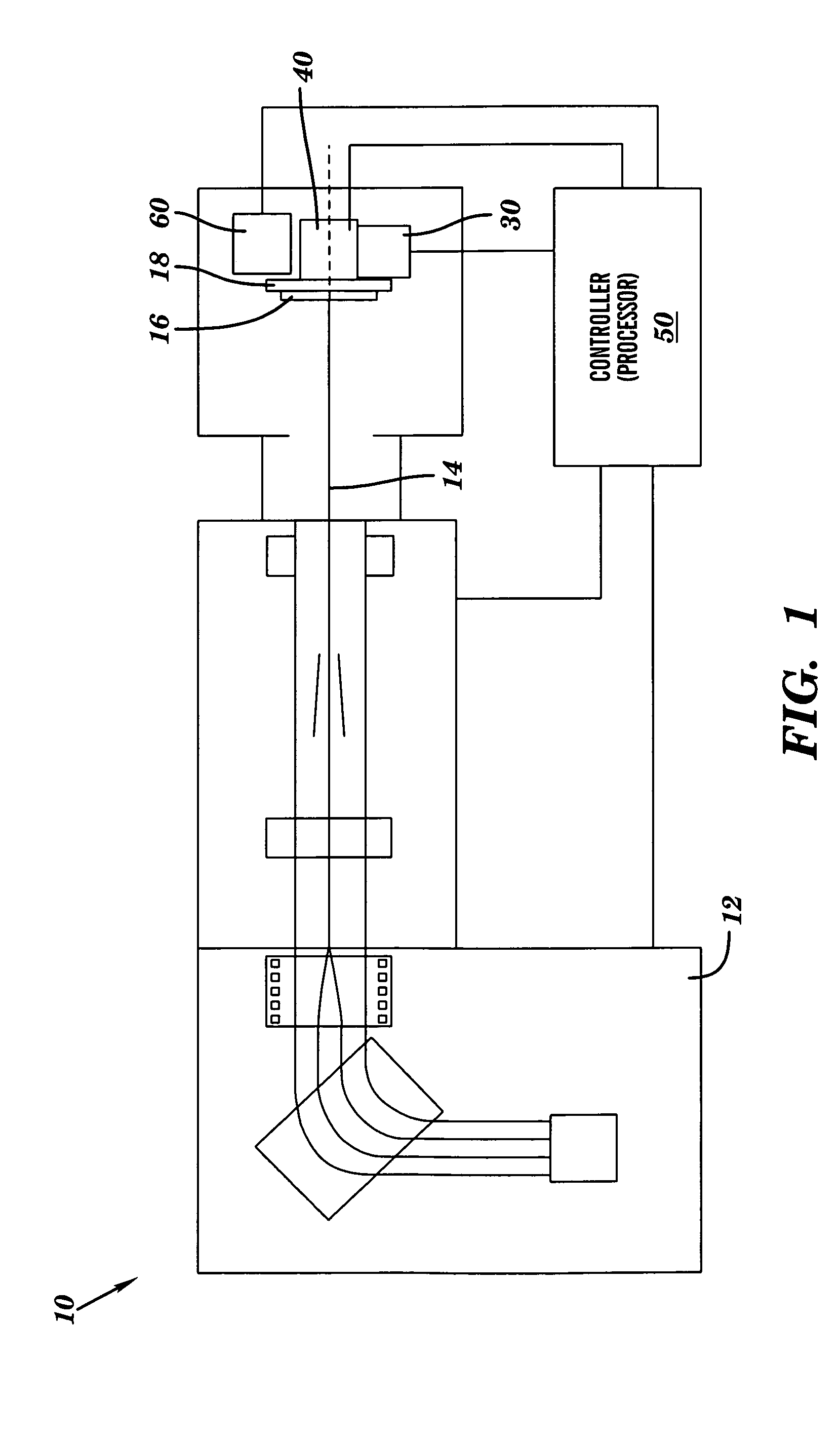
[0021]Referring to the drawings, FIG. 1 illustrates an ion implanter system 10 for conducting uniform dose ion implantation of a target (i.e., wafer) with an ion beam. According to the invention, an ion beam 14 is scanned across a target 16 at non-uniform or variable scan velocity under the control of a processor 50. Ion implanter system 10 includes, inter alia, a source 12 of ion beam 14 for implanting a target 16 that is mounted on a platen 18, a target scan translator 30, a target rotator 40 and processor 50.

[0022]Ion beam 14 may have any size or shape, and may be tuned or at least partially un-tuned according to the invention. However, the beam must have non-zero beam current at the position where the center of the target will be scanned. It is preferred, but not essential, that the beam is as wide as the target. If the beam is not as wide as the target, the number of orientations increases greatly. Ion beam 14 has an ion beam profile that indicates the ability of the ion beam t...


PUM


Abstract

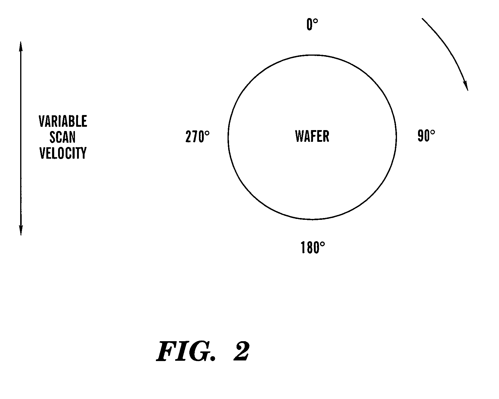
A system, method and program product for enhancing dose uniformity during ion implantation are disclosed. The present invention is directed to allowing the use of an at least partially un-tuned ion beam to obtain a uniform implant by scanning the beam in multiple rotationally-fixed orientations (scan directions) of the target at variable or non-uniform scan velocities. The non-uniform scan velocities are dictated by a scan velocity profile that is generated based on the ion beam profile and / or the scan direction. The beam can be of any size, shape or tuning. A platen holding a wafer is rotated to a new desired rotationally-fixed orientation after a scan, and a subsequent scan occurs at the same scan velocity profile or a different scan velocity profile. This technique may be used independently or in conjunction with other uniformity approaches to achieve the required level of uniformity.

Description

[0001]This application claims the benefit of U.S. Provisional Application No. 60 / 528,083, filed Dec. 9, 2003.BACKGROUND OF THE INVENTION[0002]1. Technical Field[0003]The described invention relates generally to controlling dose uniformity during ion implantation. More particularly, the described invention is directed to controlling the uniformity and dose of a semiconductor wafer by using variable scan velocity in multiple scan directions and is particularly suited for low energy implant applications.[0004]2. Related Art[0005]Ion implantation processes typically require a uniform and consistent dose or amount of ions to be implanted into a semiconductor wafer. Dose is generally a function of ion beam current density and time that the wafer spends in front of an ion beam. Current serial implanters provide an ion beam that is horizontally either an electrostatically scanned spot beam or a uniform ribbon beam. Serial implanters may also use a magnetically scanned spot beam, and a dual ...

Claims


Application Information

Patent Timeline
Patent Type & Authority Patents(United States)
IPC IPC(8): G21K5/10H01J37/08
CPCH01J37/3023H01J37/304H01L21/265H01J37/3171H01J2237/20214H01J2237/31703
Inventor RENAU, ANTHONYOLSON, JOSEPH C.SMATLAK, DONNA L.LU, JUN
Owner VARIAN SEMICON EQUIP ASSOC INC
Learn More