Lithographic apparatus and device manufacturing method

a technology of lithographic apparatus and manufacturing method, which is applied in the direction of printers, dynamo-electric machines, instruments, etc., can solve the problems of large number of restrictions, inadvisable presence of conditioned compartments, and restriction of materials that can be applied, so as to reduce vibrations of conditioned compartments, improve the performance of lithographic apparatus, and accurate projection of desired patterns on the substrate

Inactive Publication Date: 2007-01-09
ASML NETHERLANDS BV
View PDF10 Cites 11 Cited by
  • Summary
  • Abstract
  • Description
  • Claims
  • Application Information

AI Technical Summary

Benefits of technology

[0010]In a drive arrangement as described by the present invention, the first part of the first drive unit, being connected to the object table, is shielded from the second drive unit by a wall. Therefore, less stringent conditions regarding contamination or the use of materials can be applied to the second drive unit. Examples of such components or devices include the mask table or substrate table, the positioning devices including motors for performing the step and scan process. The requirement of having a conditioned atmosphere surrounding the mask or substrate results in a large number of restrictions that have to be dealt with during the design of these components or devices. For example, in order to maintain the required temperature in the apparatus, it may be desirable to restrict the heat generated by the motors and to remove it by proper cooling. The strict requirements regarding contamination may also lead to a restriction in the materials that can be applied. For example, in order to avoid outgassing, it may be desirable to shield components such as permanent magnets. Due to the presence of the wall separating the second drive unit from the object table, less stringent conditions can also be applied for the bearing of the second drive, i.e. a ball bearing could be applied instead of an air bearing. The wall may also, to some extent, reduce the risk of contamination by particles.
[0020]According to another embodiment of the invention, a drive arrangement and a positioning device are presented that can easily be assembled and disassembled. The particular drive arrangements described have a first part and a second part that can be mounted onto each other without having to disassemble one of said first and second part. Different embodiments having such properties are described, by way of example, in the accompanying figures. Although all of the cross-sectional XZ-views of the embodiments shown in the figures have a wall separating the first and second part, it will be appreciated that the presence of the wall is not mandatory for proper operation of the drive itself.

Problems solved by technology

Since such motors are generally quite large and heavy, their presence inside the conditioned compartment is not advisable.
An additional complication may be the requirement of a bearing for the part of the commutating motor located inside the enclosed chamber.
The requirement of having a conditioned atmosphere surrounding the mask or substrate results in a large number of restrictions that have to be dealt with during the design of these components or devices.
The strict requirements regarding contamination may also lead to a restriction in the materials that can be applied.
This force should be exerted continuously, i.e. at a 100% duty cycle resulting in an important source of dissipation.
Furthermore, they result in a reduced dynamic performance of the drive unit.
In case the wall separating the first part of the first drive unit from the second part from the first drive unit is in the horizontal plane, the weight of the wall may cause the wall to bent downwards if no measures are taken.

Method used


Image

  • Lithographic apparatus and device manufacturing method
  • Lithographic apparatus and device manufacturing method
  • Lithographic apparatus and device manufacturing method

Examples


Embodiment Construction

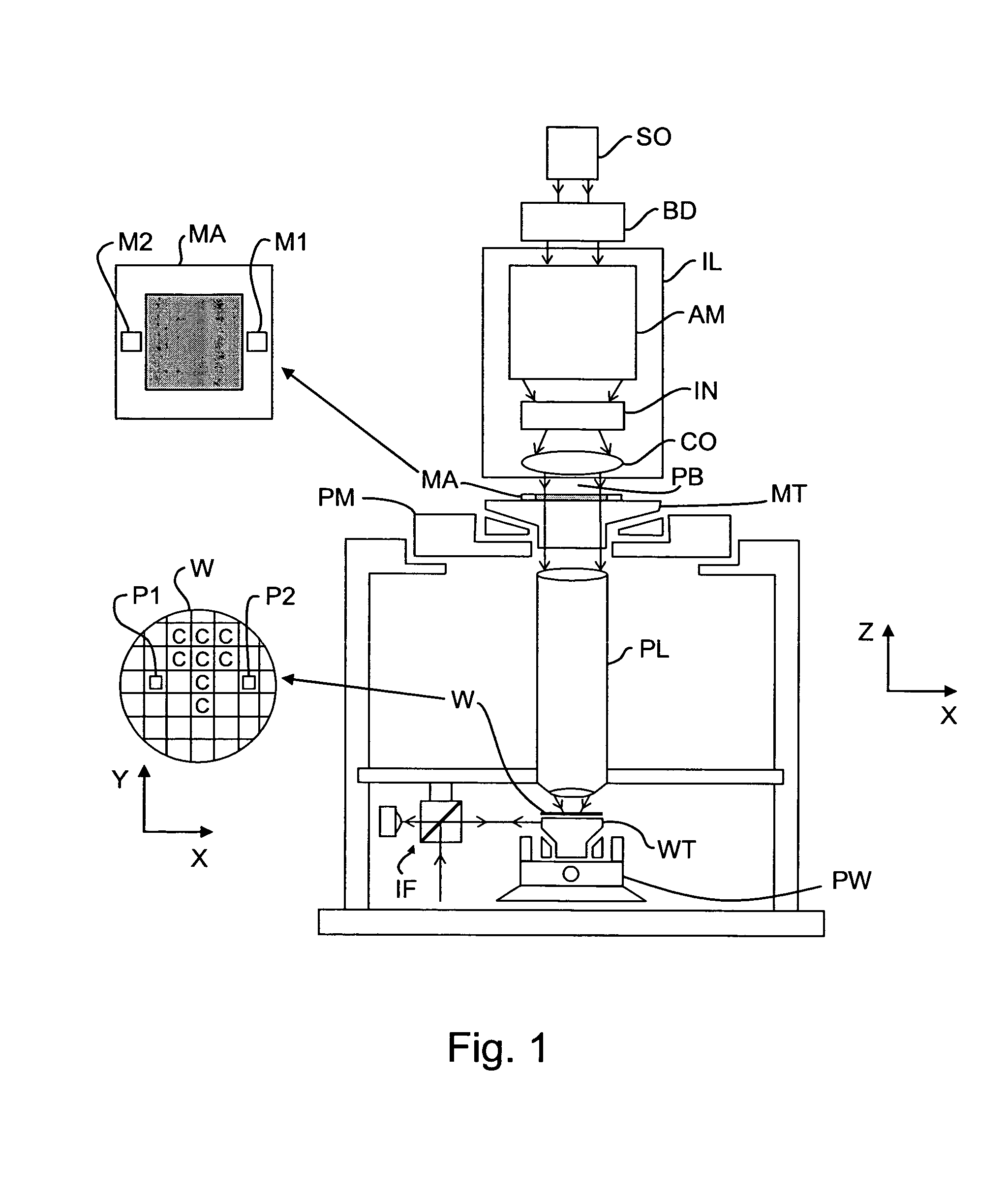
[0052]FIG. 1 schematically depicts a lithographic apparatus according to an embodiment of the invention. The apparatus includes an illumination system (illuminator) IL configured to provide a beam PB of radiation (e.g. UV radiation or EUV radiation) and a first holding structure (e.g. a mask table) MT configured to support a patterning device (e.g. a mask) MA and connected to first positioning device PM configured to accurately position the patterning device with respect to the projection system, (“lens”), item PL. The apparatus also includes a substrate table or holder (e.g. a wafer table) WT configured to hold a substrate (e.g. a resist-coated wafer) W and connected to second positioning device PW configured to accurately position the substrate with respect to the projection system, (“lens”), item PL, the projection system (e.g. a refractive projection lens) PL being configured to image a pattern imparted to the beam of radiation PB by patterning device MA onto a target portion C ...


PUM

PropertyMeasurementUnit
wavelengthaaaaaaaaaa

Abstract

A lithographic apparatus having a positioning device that facilitates the maintenance of a conditioned environment, is presented. Embodiments of the invention include a combination of a first drive unit and a second drive unit for positioning an object table in a lithographic apparatus. The first drive unit has a first part connected to the object table and a second part connected to a first part of the second drive unit. First and second part of the first drive unit are separated from each other by a wall. Maintaining a conditioned environment surrounding the object is thereby facilitated.

Description

BACKGROUND OF THE INVENTION[0001]1. Priority Information[0002]This application claims priority from European Patent Application No. 03077439.2, filed Aug. 4, 2003, the contents of which is herein incorporated by reference in its entirety.[0003]2. Field of the Invention[0004]The present invention relates to lithographic apparatus and methods[0005]3. Description of the Related Art[0006]A lithographic apparatus is a machine that applies a desired pattern onto a target portion of a substrate. Lithographic apparatus can be used, for example, in the manufacture of integrated circuits (ICs). In that circumstance, a patterning device, such as a mask, may be used to generate a circuit pattern corresponding to an individual layer of the IC, and this pattern can be imaged onto a target portion (e.g. including part of, one or several dies) on a substrate (e.g. a silicon wafer) that has a layer of radiation-sensitive material (resist). In general, a single substrate will contain a network of adj...

Claims


Application Information

Patent Timeline
Patent Type & Authority Patents(United States)
IPC IPC(8): G03B27/42G03B27/58G03B27/62H02K41/00G03F7/20H01L21/027H01L21/68H02K41/03
CPCG03F7/70758G03F7/70916G03F7/70875
Inventor DE WEERDT, ROBRECHT EMIEL MARIA LEONIA
Owner ASML NETHERLANDS BV
Why Eureka
Try Eureka