Method for the planning and delivery of radiation therapy

a radiation therapy and computerized technology, applied in radiation therapy, diaphragm/collimeter handling, therapy, etc., can solve the problems of fixed-field delivery and rotational delivery, and achieve the effect of reducing the number of patients

Inactive Publication Date: 2007-01-09
UNIV OF MARYLAND BALTIMORE
View PDF11 Cites 87 Cited by
  • Summary
  • Abstract
  • Description
  • Claims
  • Application Information

AI Technical Summary

Benefits of technology

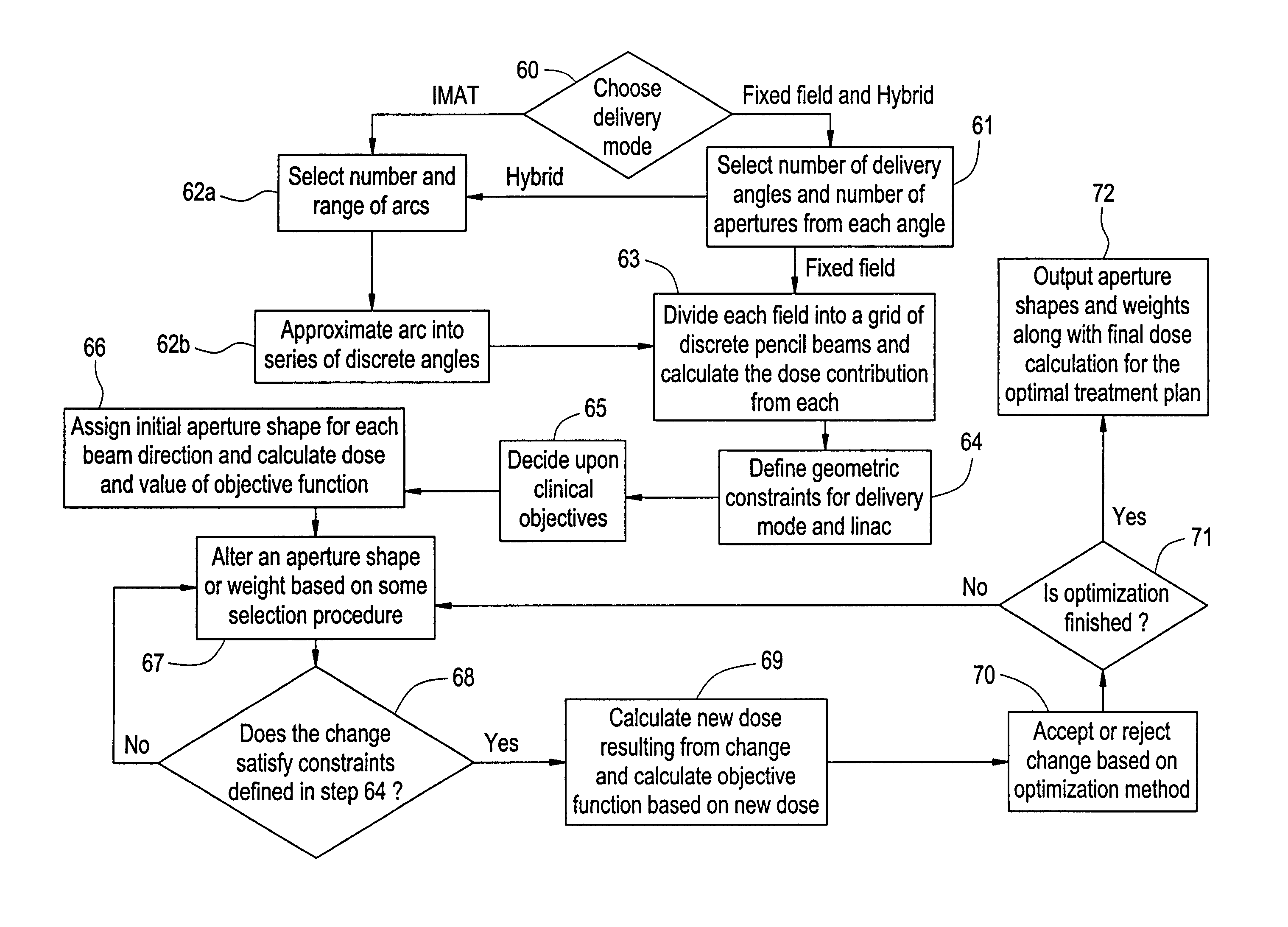
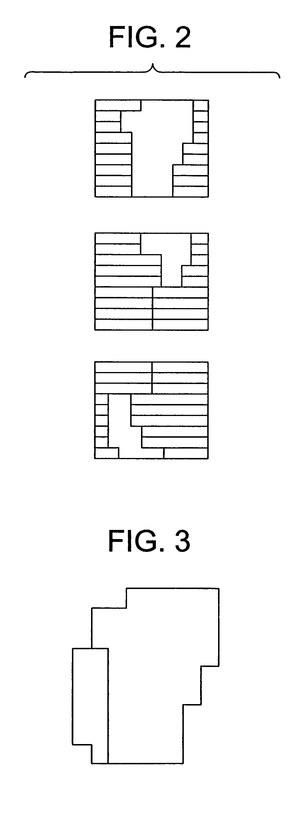
[0019]For each delivery angle, the maximum extent of the beam aperture is determined based on the beam's eye view of the target with sufficient margins. This beam is then divided into a grid of small beamlets called pencil beams. The dose distribution from each of these pencil beams is calculated using any conventional dose calculation method and stored on an appropriate medium, such as a hard drive. At the start of the optimization, all apertures in the same beam direction are set to the same shape as the maximum extent of the beam. These apertures are then optimized by an optimization algorithm. The optimization process generally involves modifying the shape or weight of the apertures, determining if the modification violates the delivery constraints, and, finally, accepting and rejec

Problems solved by technology

For instance, fixed-field delivery would have constraints imposed by the MLC.
Rotational delivery woul

Method used


Image

  • Method for the planning and delivery of radiation therapy
  • Method for the planning and delivery of radiation therapy
  • Method for the planning and delivery of radiation therapy

Examples


Embodiment Construction

[0025]Referring to FIG. 4, a linear accelerator (linac) 1 which is a device capable of controlled delivery of radiation to a patient in need of radiation therapy. The radiation exits through the end of the treatment head which is mounted on the gantry (not shown). In some linacs, the treatment head is equipped with a multi-leaf collimator (MLC) which shapes the radiation field. A linac has a control unit in a housing. A linac has a gantry which can rotate about a horizontal axis H of rotation around the patient who is lying on the bed. A linac emits a beam of radiation which is aimed at the patient. The beam of radiation can be photons, electrons, or any other type of radiation used for therapy.

[0026]During treatment, the radiation beam is directed on a part of the treatment area on the patient. The gantry can rotate about a horizontal axis of rotation; thus allowing for a change in the angle of treatment.

[0027]A MLC has multiple thin leafs which can be made of tungsten alloy or oth...


PUM


Abstract

A new optimization method for generating treatment plans for radiation oncology is described and claimed. This new method works for intensity modulated radiation therapy (IMRT), intensity modulated arc therapy (IMAT), and hybrid IMRT.

Description

[0001]This application claims benefit of Provisional Application No. 60 / 338,118 filed Dec. 3, 2001; the disclosure of which is incorporated herein by reference.[0002]This invention was made with the support of the U.S. government under Grant Number R29CA66075 awarded by NIH. The U.S. government has certain rights in this invention.[0003]A computer listing of a program according to an exemplary embodiment of the invention is submitted herewith in a CD-ROM as an Appendix to this application. The contents of the CD-ROM are incorporated by reference. The computer program is subject to copyright protection.BACKGROUND OF THE INVENTION[0004]1. Field of the Invention[0005]The present invention relates to a computerized method for the planning and delivery of radiation therapy. In particular, it is a computerized method that determines the optimal radiation treatment plan for a patient using specified clinical objectives.[0006]2. Description of Related Art[0007]Radiation therapy, in general,...

Claims


Application Information

Patent Timeline
IPC IPC(8): A61N5/10
CPCA61N5/1031A61N5/1047A61N2005/1035A61N5/1042
Inventor EARL, MATT A.SHEPARD, DAVID M.YU, XINSHENG
Owner UNIV OF MARYLAND BALTIMORE
Why Eureka
Try Eureka