
Collaborative environment implemented on a distributed computer network and software therefor

a technology of distributed computer network and collaborative environment, applied in the field of distributed computer system, can solve the problems of difficult for the components of the u.s. military to interoperate, difficult for the various military components to share a homogeneous view of tactical information, and variable users to be unable to coordinate their efforts. to achieve the effect of facilitating the exchange of information

Inactive Publication Date: 2007-01-09
THE UNITED STATES OF AMERICA AS REPRESENTED BY THE SECRETARY OF THE NAVY
View PDF18 Cites 142 Cited by
  • Summary
  • Abstract
  • Description
  • Claims
  • Application Information

AI Technical Summary

Benefits of technology

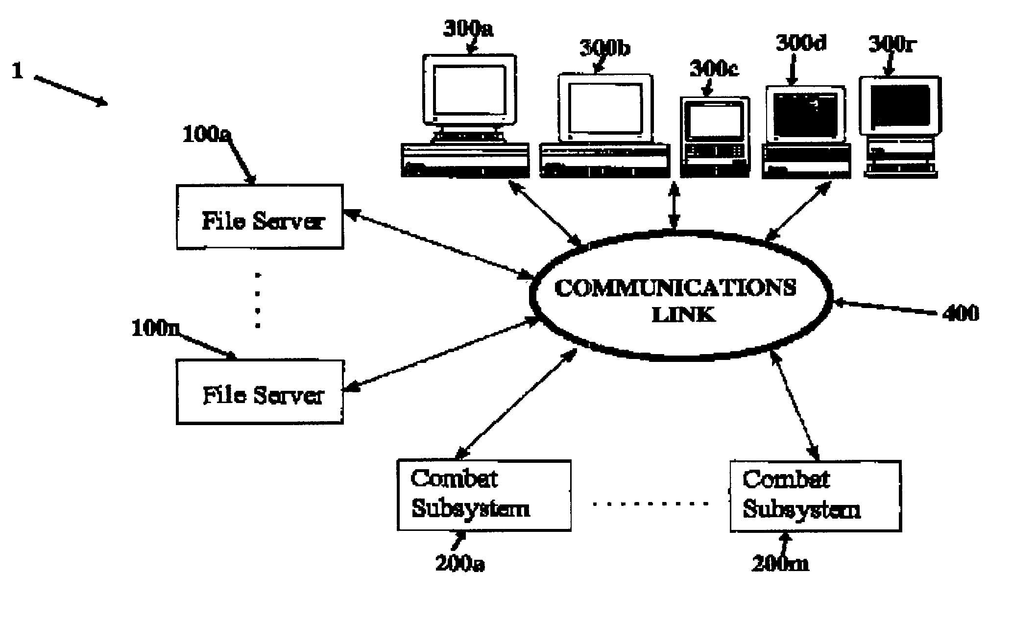
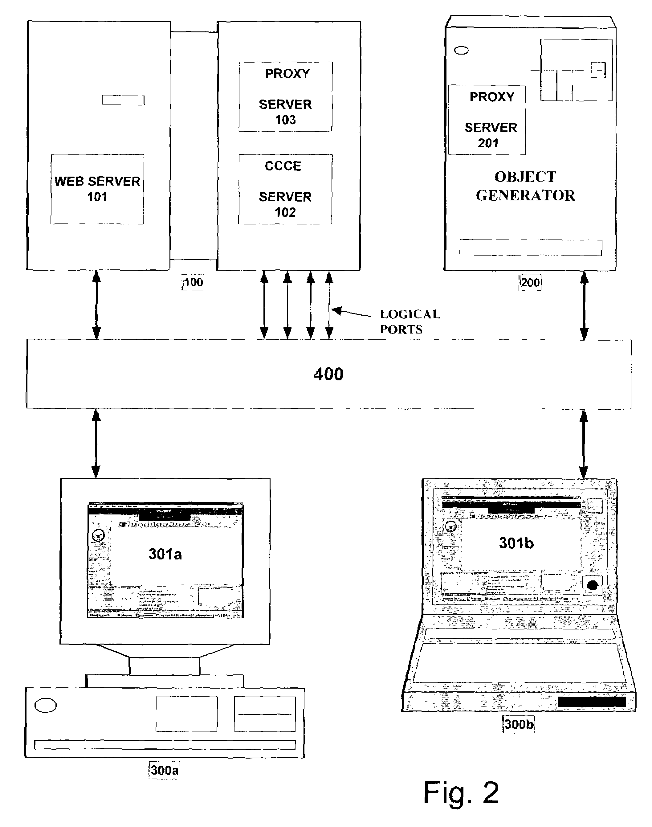
[0028]In another aspect, the present invention provides a Collaborator computer collaborative environment (CCE) instantiated by a distributed computer system that facilitates interchange of information between two or more users sitting at respective computer terminals disposed in the collaborative environment, including first and second Collaborator CCE clients, a Collaborator CCE server, and a communications channel operatively coupling the first and second Collaborator CCE clients to the Collaborator CCE server. Advantageously, the first Collaborator CCE client instantiates an applet generating a message object having an embedded group identifier and an associated privilege level, the Collaborator CCE server receives and stores the message object, and the Collaborator CCE server outputs the message object to the second Collaborator CCE when the second Collaborator CCE client is a member of the group associated with the group identifier and the privilege level of the second Collaborator CCE client exceeds the privilege level of the message object. If desired, the computer system further includes an object generator server instantiated by an object server computer different than the computer instantiating the Collaborator CCE server, the object generator server generating a first object, and the first Collaborator CCE client instantiates a first applet, which receives the first object from the object generator server via the communications is channel. Alternatively, the computer system further includes an object generator server instantiated by an object server computer different than the computer instantiating the Collaborator CCE server, the object generator server generating a first object, the computer instantiating the Collaborator CCE server instantiates a proxy server responsive to commands from the first Collaborator CCE and receives the first object via the communications channel, and the first Collaborator CCE client receives the first object from the proxy server via the communications channel. In an exemplary case, the first Collaborator CCE client instantiates first and second applets communicating with one another.
[0029]According to a still further aspect, the present invention provides software, i.e., machine readable code stored in a memory for converting a general purpose computer system including at least first, second, and third computers operatively coupled to one another by a communications channel to instantiate a Collaborator computer collaboration environment (CCE) facilitating collaboration between users co-located with the second and third computers. Preferably, the machine readable code instantiates a Collaborator CCE server on the first computer, the Collaborator CCE server providing a web page invoking selected portions of the machine readable code, and first and second Collaborator CCE clients on the second and third computers, respectively, in response to receiving the web page from the Collaborator CCE server, wherein each of the first and second Collaborator CCE generates first and second message objects containing a group identifier and a privilege level, respectively, and the Collaborator CCE receives the first and second message objects, stores the first and second message objects, and transmits the first and second message objects to the second and first Collaborator CCE clients, respectively, when the receiving one of the first and second Collaborator CCE clients is a member of a group corresponding to the group identifier and when the privilege level of the receiving one of the Collaborator CCE clients equals or exceeds the privilege level of the respective one of the first and second message objects.

Problems solved by technology

Moreover, even when interoperability concerns are satisfied, this only assures that information can be transferred from the source of the information to the user of the information; there still exists the concern that the various users will be unable to coordinate their efforts, i.e., collaborate with one another, in planning and executing the mission and in critiquing completed missions.
The number of different systems that must be interconnected varies with each Joint Mission, making it extremely difficult for the components of the U.S. Military to interoperate.
In particular, it is extremely difficult for the various military components to share a homogeneous view of tactical information.
The degree of difficulty is often increased when the various military components are physically separated from one another over long distances.
The problem is exacerbated when armies from several nations, e.g., a NATO force, are endeavoring to interoperate.
It will be appreciated that the foregoing discussion assumes that several versions of the same program can be installed on the various computers being networked to one another; the problem is exacerbated when the computer systems, which must be networked, are running incompatible operating systems.
As a result, each approach has specific drawbacks and benefits.
The drawback of this approach is that it requires that all machines be set up in exactly the same manner including identical hardware operating systems and applications.
As a result, communication between the people using the system quickly breaks down because they are each seeing different things on their respective screens, thereby making this method of conferencing unusable.
A drawback of this method of conferencing is that it requires a large amount of information to be transmitted in the form of all or part of the screen memory and as a result it is relatively slow and inflexible.
Also, because all the users in the conference share the same information, all users must possess sufficient hardware and software to display the screen information including complex graphical representations.
As a result, if one user selects text in a word processor and another user types the key, both operations will be considered as originating from one user, and the data may be accidentally destroyed.
Thus, the user input and visual display systems are not truly collaborative wherein multiple users may modify the data concurrently.
In mid-level conferencing, application primitives (units of information necessary to duplicate the user's operation on remote machines) are sent from one machine to the other, which has the following drawbacks:1. some centralized control is necessary to implement the exchange of primitives;2. high performance (speed) computers and expensive computer systems are necessary to implement such mid-level conferencing in real time; and3. with a centralized architecture, performance limitations are incurred because at least two message transmission delays result between the originating workstation and the controller and then back.
In summary, U.S. Pat. No. 5,206,934 concludes that all of these approaches have serious drawbacks.
In the case of remote systems, a master controller requires interpretation of screen change commands, which can be slow when the high data volume is relatively high.
In primitive passing systems, the problem is alleviated but at the cost of central processing with high performance equipment.
However, neither NetMeeting nor any of the other approaches discussed above, permits active content, links, and GUI objects, nor do these programs and collaboration methods allow for central data storage, logging, and filtering.

Method used


Image

  • Collaborative environment implemented on a distributed computer network and software therefor
  • Collaborative environment implemented on a distributed computer network and software therefor
  • Collaborative environment implemented on a distributed computer network and software therefor

Examples


Embodiment Construction

[0038]One of the principal objects of the present inventions, although certainly not the only one, is to provide a Universal Distributed Display Capability (UDDC) for operating substantially all military applications on any commercial off the shelf (COTS) based system supporting a JAVA™ enabled browser. A preferred embodiment of the present invention accomplishes this objective through a software application written in JAVA™ implementing a Common Collaboration Environment (CCE). Beneficially, the combination of the CCE software and a JAVA™ enabled browser at each user location permit collaboration between users of a multilayer Collaborator CCE.

[0039]In an exemplary case, the CCE software advantageously can be a JAVA™ applet. The CCE application according to the present invention (hereinafter Collaborator CCE) allows a large organization, e.g., a far-flung Government or commercial enterprise, to solve certain interoperability problems while satisfying collaboration requirements and, ...


PUM


Abstract

A Collaborator computer collaborative environment (CCE) instantiated by a computer network includes N Collaborator CCE clients and a Collaborator CCE server. Each of the N Collaborator CCE clients generates message objects each including a nested group identifier and an associated privilege level; the Collaborator CCE server filters the generated message objects and routes only those message objects to an Nth Collaborator CCE client that is a member of the respective group having the group identifier and that has a privilege greater than or equal to the associated privilege level. Corresponding software is also described.

Description

CROSS-REFERENCE TO RELATED APPLICATIONS[0001]This is a Continuation-in-Part of U.S. Ser. No. 09 / 551,364, which was filed on Apr. 17, 2000, which is a combined Continuation-in-Part of U.S. Ser. No. 09 / 296,746, which issued as U.S. Pat. No. 6,351,777 B1 on Feb. 26, 2002, U.S. Ser. No. 09 / 296,757, and U.S. Ser. No. 09 / 296,802, now U.S. Pat. No. 6,463,460 all of which were filed on Apr. 23, 1999. Moreover, this patent application claims the benefit of priority, under 35 U.S.C. §119(e), to Provisional Patent Application No. 60 / 109,453, which was filed on Nov. 23, 1998, and which is incorporated, in its entirety, herein by reference.STATEMENT OF GOVERNMENT INTEREST[0002]The invention described herein was made in the performance of official duties by employees of the Department of the Navy and, thus, the invention disclosed herein may be manufactured, used, licensed by or for the Government for governmental purposes without the payment of any royalties thereon.BACKGROUND OF THE INVENTION[0...

Claims


Application Information

Patent Timeline
IPC IPC(8): G06F15/16
CPCG06Q10/10H04L65/4015H04L67/12H04L67/14H04L65/403H04L12/1822
Inventor SIMONOFF, ADAM J.HEBERT, JR., JULIAN B.
Owner THE UNITED STATES OF AMERICA AS REPRESENTED BY THE SECRETARY OF THE NAVY
Learn More