Multi-carrier CDMA communication device, multi-carrier CDMA transmitting device, and multi-carrier CDMA receiving device

Inactive Publication Date: 2007-01-16
MITSUBISHI ELECTRIC CORP
View PDF8 Cites 145 Cited by
  • Summary
  • Abstract
  • Description
  • Claims
  • Application Information

AI Technical Summary

Benefits of technology

[0029]It is an object of the present invention to provide a multi-carrier CDMA communication apparatus capable of realizing an excellent bit error rate characteristic, even when the expanse of the delayed wave is not fitted in the guard interval, and the transmission signal from the base station is affected by the frequency selective fading on the transmission line.
[0030]It is another object of the present invention to provide a multi-carrier CDMA communication apparatus capable of realizing improvement of the input signal quality, by using a delayed wave, when the level of the delayed wave is larger than the preceding wave.
[0031]It is still another object of the present invention to provide a multi-carrier CDMA communication apparatus capable of changing the frequency spreading rate, while maintaining the condition that the frequency spreading codes allocated for each user or for each channel to be used are orthogonal to each other.

Problems solved by technology

For example, in the mobile communication system, radio wave reflects, diffracts and scatters due to surrounding buildings and geographical features, and incoming waves (multi-path waves) through a plurality of transmission lines interfere with each other, and hence an impulse response of the frequency selective fading transmission line occurs.
In the conventional multi-carrier CDMA communication apparatus, however, the expanse of the delayed wave is large depending on the situation of the transmission line, and sometimes the expanse of the delayed wave may not be fitted in the guard interval.
In such an instance, there is a problem in that the apparatus is affected by the frequency selective fading, thereby the influence of interference increases in the symbol, and an excellent bit error rate characteristic cannot be obtained.
There is another problem in that when the level of the delayed wave is larger than the preceding wave, the delayed wave is not utilized for increasing the quality of the input signal (for example, a signal power to interference power ratio (SIR)).
In the conventional multi-carrier CDMA communication apparatus, however, it is necessary that the frequency spreading codes are orthogonal to each other, and since the frequency spreading rate is fixed, there is a problem in that the information rate cannot be changed adaptively.
When hand-over is performed between sectors and between cells, so that communication is not broken off at the time of reception by a mobile station (terminal), it is necessary to change the frequency to be used on the transmission line, thereby causing a problem in that the frequency efficiency decreases.

Method used


Image

  • Multi-carrier CDMA communication device, multi-carrier CDMA transmitting device, and multi-carrier CDMA receiving device
  • Multi-carrier CDMA communication device, multi-carrier CDMA transmitting device, and multi-carrier CDMA receiving device
  • Multi-carrier CDMA communication device, multi-carrier CDMA transmitting device, and multi-carrier CDMA receiving device

Examples


first embodiment

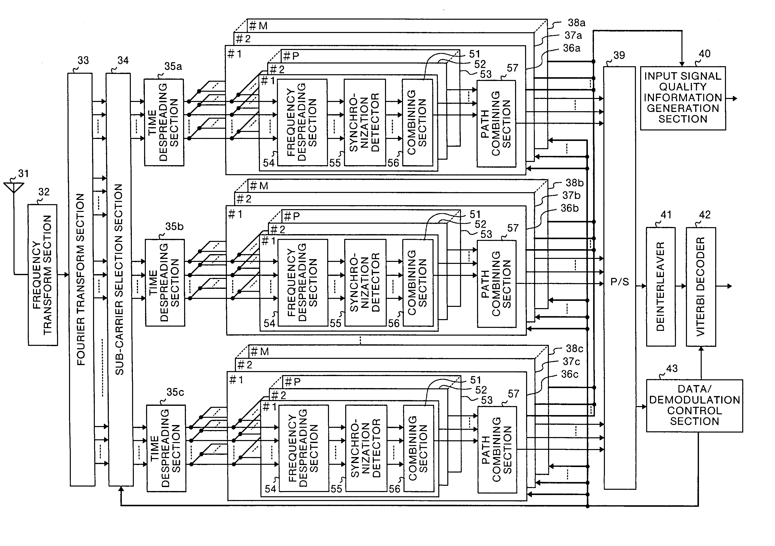
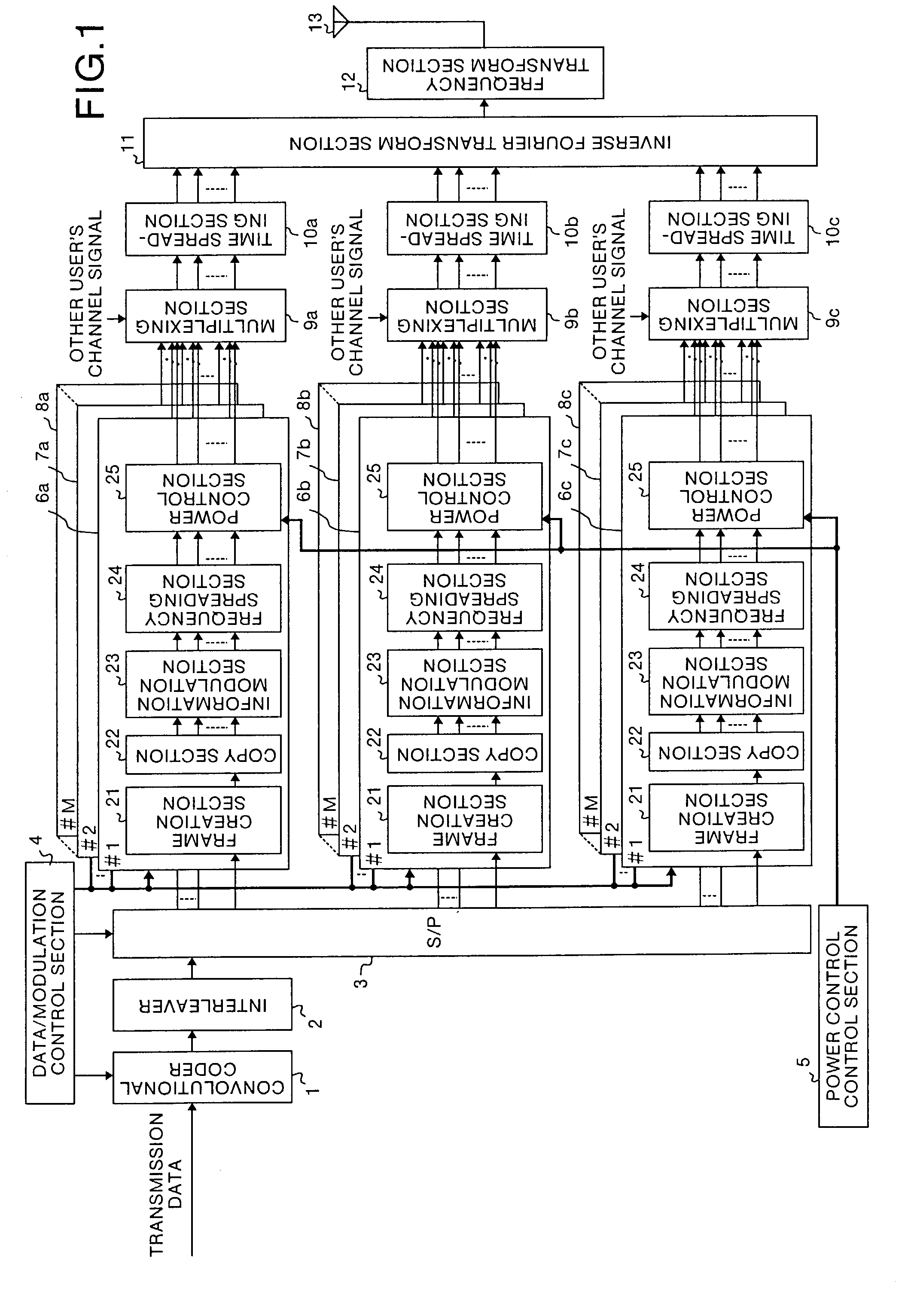
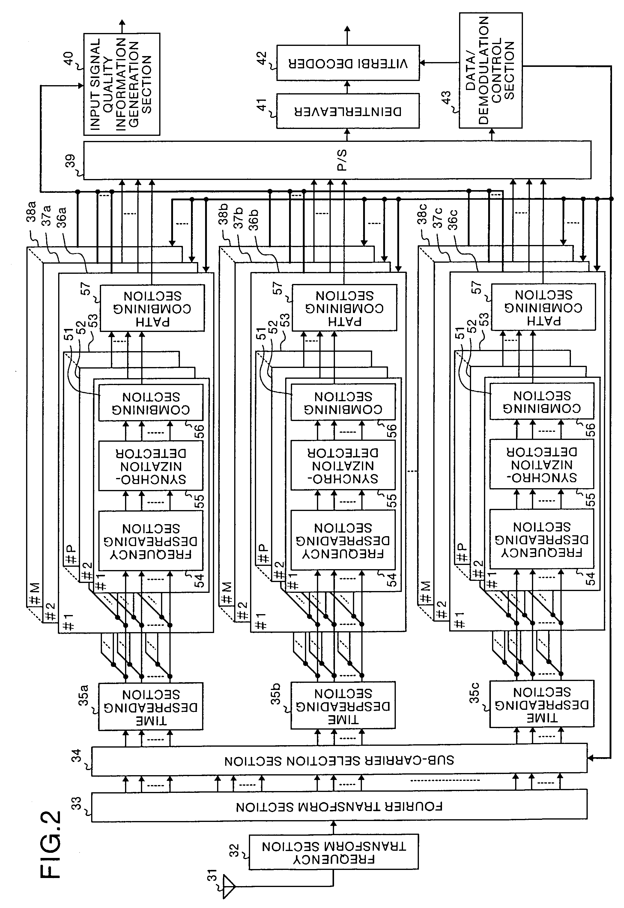
[0101]FIG. 1 and FIG. 2 are diagrams which show the construction of a multi-carrier CDMA communication apparatus of the present invention in the first embodiment. FIG. 1 is a diagram which shows the construction of a multi-carrier CDMA transmitter and FIG. 2 is a diagram which shows the construction of a multi-carrier CDMA receiver in this embodiment.

[0102]In FIG. 1, reference symbol 1 denotes a convolutional coder, 2 denotes an interleaver, 3 denotes a serial / parallel conversion section (hereinafter, referred to as S / P), 4 denotes a data / modulation control section, 5 denotes a power control control section, 6a, 6b, 6c, 7a, 7b, 7c, . . . , 8a, 8b and 8c denote first, second, and Nscg-th sub-carrier group modulation processing sections provided for each channel, 9a, 9b and 9c denote multiplexing sections, 10a, 10b and 10c denote time spreading sections, 11 denotes an inverse Fourier transform section, 12 denotes a frequency transform section, 13 denotes an antenna, 21 denotes a frame...

second embodiment

[0148]A multi-carrier CDMA communication apparatus in the second embodiment has the same construction as that in the first embodiment, with the exception that the relation between the sub-carrier and the frequency spreading code arranged on the frequency axis is different. Only the portion different from that of the first embodiment will be explained herein.

[0149]FIG. 22 is a diagram which shows the relation between a sub-carrier and a frequency spreading code group allocated for each sub-carrier. In this second embodiment, differing from the first embodiment, the frequency spreading code is allocated, with a certain frequency interval (sub-carrier interval), while keeping the orthogonality and hierarchical relationship between the frequency spreading codes. Sequence elements shown in FIG. 10 are periodically allocated, while keeping the orthogonality and hierarchical relationship between the frequency spreading codes shown in FIG. 9.

[0150]Thus, in the second embodiment, the same ef...

third embodiment

[0152]A multi-carrier CDMA communication apparatus in the third embodiment has the same construction as that of the first embodiment, with the exception that the internal construction and the operation of the synchronization detector 55, the combining section 56 and the path combining section 57 of the receiver are different. Only the portion different from that of the first embodiment will be explained herein.

[0153]FIG. 23 is a diagram which shows the construction of the synchronization detector 55 in the third embodiment. In FIG. 23, reference symbols 191, 194 and 197 denote transmission line estimation sections, 192, 195 and 198 denote complex conjugate calculation sections, and 193, 196 and 199 denote multipliers. The synchronization detector 55 receives sub-carrier signals (1, 1) to (1, Nsub) after the inverse spreading, and performs synchronization detection, using the known sequence added for each slot in the frame. The synchronization detector 55 outputs the sub-carrier sign...


PUM


Abstract

The transmitter comprises a data / modulation control section (4) which sets predetermined parameters necessary for demodulation processing, sub-carrier group modulation processing sections (6a to 8c) which perform frequency spreading for each sub-carrier signal in the sub-carrier group, and time spreading sections (10a to 10c) which multiplex all signals after the modulation processing and the frequency spreading for each sub-carrier signal, and perform time spreading with respect to the multiplexed signals. The receiver comprises time despreading sections (35a to 35c) which perform time despreading for each sub-carrier signal, and sub-carrier group demodulation processing sections (36a to 38c) which perform frequency despreading for each sub-carrier signal after the time despreading.

Description

TECHNICAL FIELD[0001]The present invention relates to a communication apparatus in a mobile communication system which adopts a multiple access scheme, using a multi-carrier CDMA method. More particularly, the present invention relates to a multi-carrier CDMA communication apparatus, a multi-carrier CDMA transmitting apparatus and a multi-carrier CDMA receiving apparatus, which can obtain excellent bit error rate characteristic even in a communication environment affected by frequency selective fading.BACKGROUND ART[0002]A conventional multi-carrier CDMA communication apparatus will now be explained. As a communication apparatus in a mobile communication system which adopts the multiple access scheme, using the multi-carrier CDMA method, there can be mentioned for example the one described in the literatures “Performance comparisons of coherent SC / DS-CDMA, MC / DS-CDMA, MC-CDMA on down-link broadband radio packet transmission”, The Institute of Electronics, Information and Communicati...

Claims


Application Information

Patent Timeline
IPC IPC(8): H04J4/00H04B1/7117H04B1/69H04B1/707H04B1/7073H04J11/00H04J13/00H04J13/20H04L5/02
CPCH04B1/692H04L5/026H04J13/0044H04J13/20H04B1/707H04B1/712H04B1/7117H04B1/7073
Inventor SANO, HIROYASUKATAOKA, NOBUHISA
Owner MITSUBISHI ELECTRIC CORP
Why Eureka
Try Eureka