Subsea intervention system, method and components thereof

a technology of subsea intervention and submerged well, which is applied in the direction of sealing/packing, drilling pipes, and wellbore/well accessories, etc., can solve the problems of reducing the production rate or even killing the well, increasing the amount of oil recovered from a given reservoir, and high cost of performing even a minor well intervention

Active Publication Date: 2007-01-23
VARCO I P INC
View PDF23 Cites 106 Cited by
  • Summary
  • Abstract
  • Description
  • Claims
  • Application Information

AI Technical Summary

Benefits of technology

[0023]In a preferred embodiment, the tubing injector includes a traction device including opposed grippers laterally moveable with respect to the coiled tubing to move in a respective chain link member of an endless loop chain into gripping engagement with the coiled tubing. A drive motor is provided for powering the endless loop chain. A plurality of roller bearings each act between the respective link member and a gripper, with each roller bearing including one or more seals subjected to subsea conditions. A pressure compensating device is provided within each shaft of the plurality of the roller bearings for subjected lubricant in a fluid passageway in the roller bearing to a fluid pressure functionally related to subsea pressure, such that a controlled pressure differential exists across the one or more seals which seal the lubricant from the subsea conditions. The pressure compensating device may include a piston movable within a bore in the shaft of the roller bearing. A seal is provided for maintaining substantially sealed engagement between the piston and the shaft to fluidly isolate the lubricant from the subsea conditions. A biasing member w

Problems solved by technology

Years of production experience have shown that close reservoir supervision and relatively minor well intervention procedures may dramatically increase the amount of oil recovered from a given reservoir.
Slight increases in the WOR may greatly reduce the production rate or even kill the well.
In deep-water subsea wells, however, the cost of performing even a minor well intervention is very high.
This high cost often makes simple intervention work prohibitively expensive.
Also, there may be a considerable amount of production time lost while awaiting the availability of a suitable deepwater rig.
It also adds a significant amount of weight to the structure and is somewhat limited in the number of tools that it can carry.
A conventional coiled tubi

Method used


Image

  • Subsea intervention system, method and components thereof
  • Subsea intervention system, method and components thereof
  • Subsea intervention system, method and components thereof

Examples


Embodiment Construction

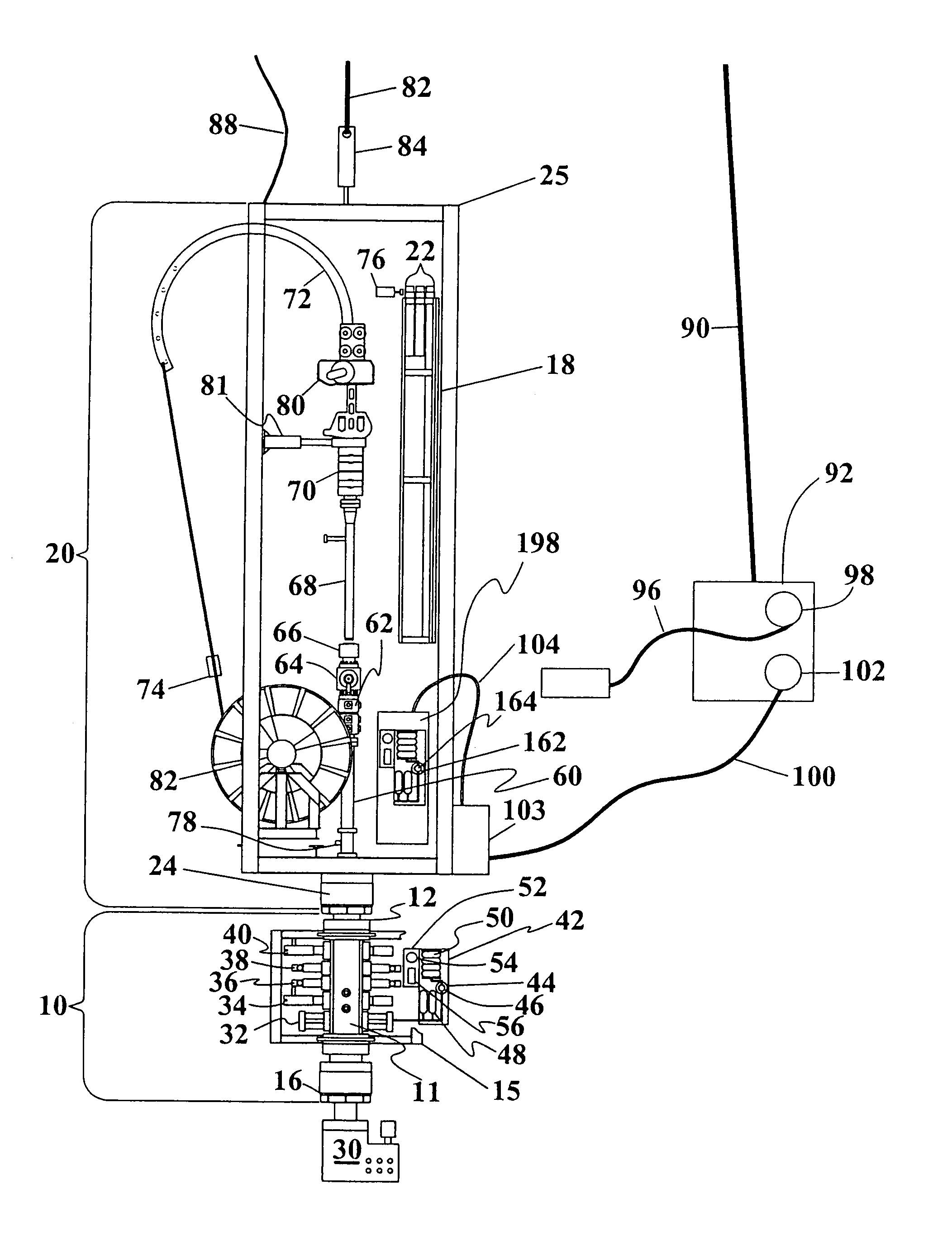
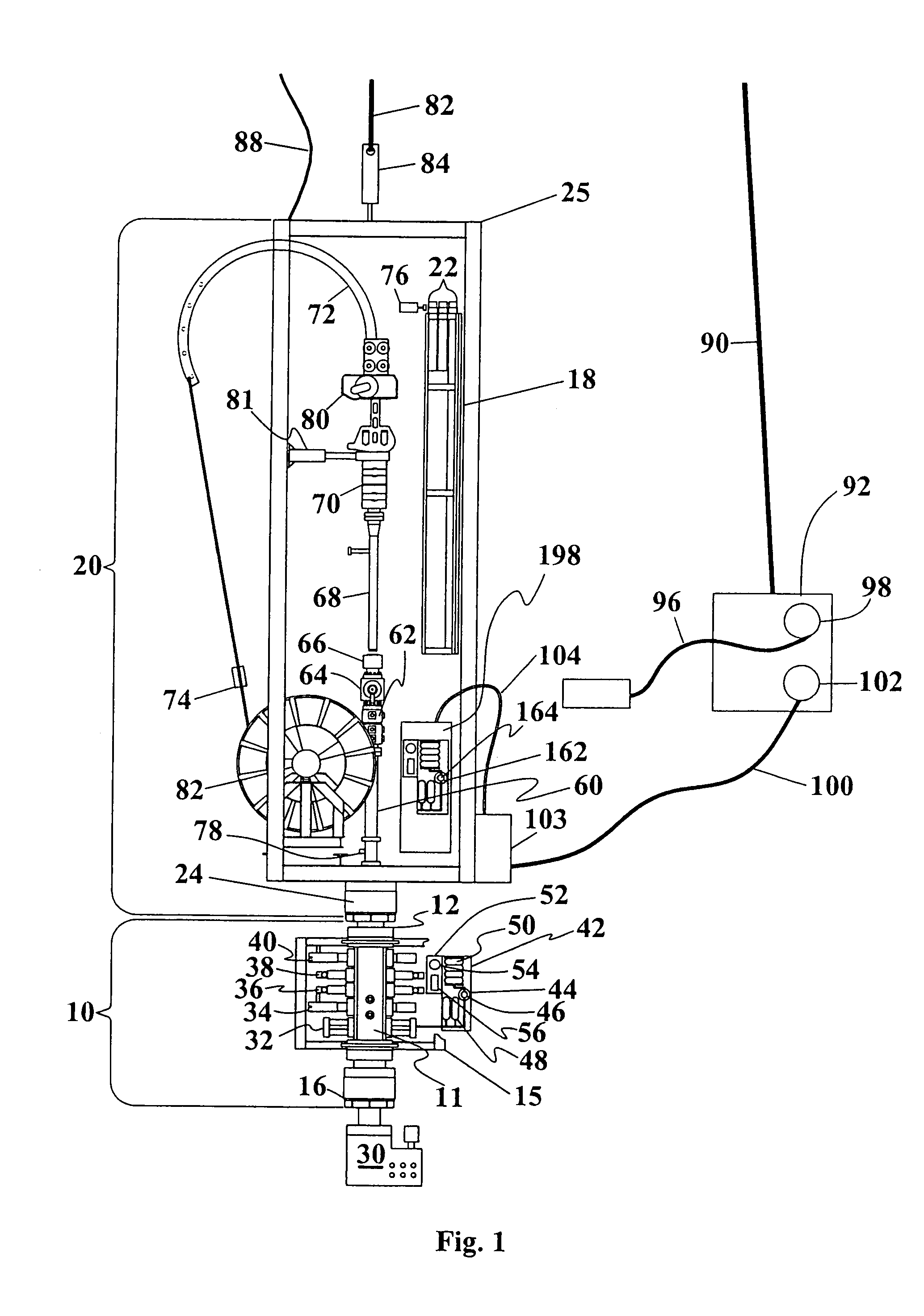
[0079]The SIM as shown in FIG. 1 consists of two basic modules. The BOP module 10 maintains control of the well during workover operations and allows a conventional BOP to be connected to the well. The coiled tubing (CT) module 20 as depicted includes a marinized injector, a quick-change reel, strippers, and a tool magazine, as discussed more fully below. All of the tools required to complete the workover may be loaded into the tool magazine while the SIM is on the deck of the ship. If necessary, additional tools may be deployed and loaded into the magazine subsea. When fully assembled, a latched SIM may be approximately 70 feet tall and weigh approximately 340,000 pounds.

[0080]The feasibility study identified major technical hurdles and a financial hurdle to overcome in order to develop the SIM. The technical hurdles included development of a marinized injector, a reliable wet connector for the coiled tubing connector, a power / control system, a system to circulate seawater, techniq...


PUM


Abstract

The subsea intervention system (SIM) includes a BOP module 10 and CT module 20. A tool positioning system 76 is used for positioning a selected subsea tool 22 stored within a rack 18 with a tool axis in line with the BOP axis, while a marinized coiled string injector 80 is moved by positioning system 81 to an inactive position. Power to the subsea electric motors 162 is supplied by an electrical line umbilical extending from the surface for powering the pumps 164, with the hydraulic system controlled by power control unit 198. The injector 80 preferably includes a pressure compensator roller bearing 220 and a pressure compensated drive system case 254.

Description

RELATED APPLICATIONS[0001]The present application incorporates by reference therein and claims priority from each of U.S. application Ser. No. 60 / 362,437, filed Mar. 7, 2002, application Ser. No. 60 / 433,259, filed Dec. 13, 2002 and application Ser. No. 60 / 425,399, filed Nov. 12, 2002.FIELD OF THE INVENTION[0002]The present field of the invention relates generally to a subsea intervention system and a method for performing subsea intervention operations. The invention further relates to improvements in the specific components of the intervention system and the interrelationship of those components in this and other intervention systems. The invention also relates to a subsea coiled tubing injector and, more particularly, to a subsea coiled tubing injector capable of achieving reliable operation at a relatively low cost, and preferably one with a pressure compensated drive system.BACKGROUND OF THE INVENTION[0003]Years of production experience have shown that close reservoir supervisio...

Claims


Application Information

Patent Timeline
IPC IPC(8): E21B29/12E21B19/14E21B19/22E21B33/072E21B33/076H04L1/00
CPCE21B7/124E21B19/146E21B33/076E21B33/072E21B19/22
Inventor FOX, PRESTONGOODE, JOHNIANKOV, IVANMARTIN, DAVIDMICHEL, ANDREWYATER, RONALD
Owner VARCO I P INC
Why Eureka
Try Eureka