Engine control arrangement for watercraft

a technology for watercraft and control arrangement, which is applied in the direction of electric control, special purpose vessels, vessel construction, etc., can solve the problems of fatigue of the rider's hand, fingers or thumbs

Active Publication Date: 2007-01-23
YAMAHA MARINE KK
View PDF71 Cites 29 Cited by
  • Summary
  • Abstract
  • Description
  • Claims
  • Application Information

AI Technical Summary

Problems solved by technology

When a rider operates such a watercraft in a reduced speed area for long periods of time, the rider's hand, fingers, or thumb can become fatigued through the prolonged manipulation of the engine power control lever.

Method used


Image

  • Engine control arrangement for watercraft
  • Engine control arrangement for watercraft
  • Engine control arrangement for watercraft

Examples


Embodiment Construction

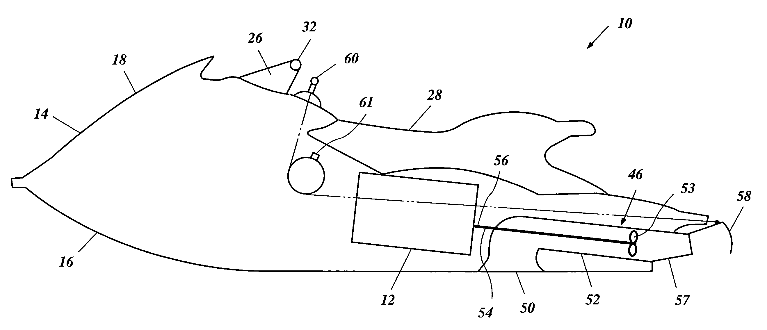
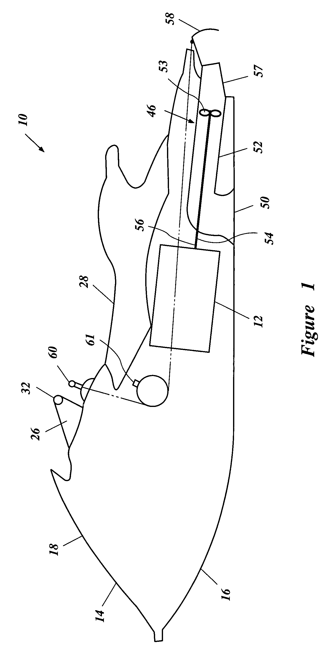
[0027]With reference to FIGS. 1–3, an overall configuration of an engine control system is described below in the environment of a personal watercraft 10. The watercraft 10 includes an engine 12 operated by the control system. The control system described below has particular utility for use with personal watercraft, and thus, the control system is described in the environment of the personal watercraft 10. However, the control system can be used with other types of vehicles, such as, for example, small jet boats and other vehicles.

[0028]With reference initially to FIG. 1, the personal watercraft 10 includes a hull 14 formed with a lower hull section 16 and an upper hull section or deck 18. The lower hull section 16 and the upper hull section 18 preferably are coupled together to define an internal cavity.

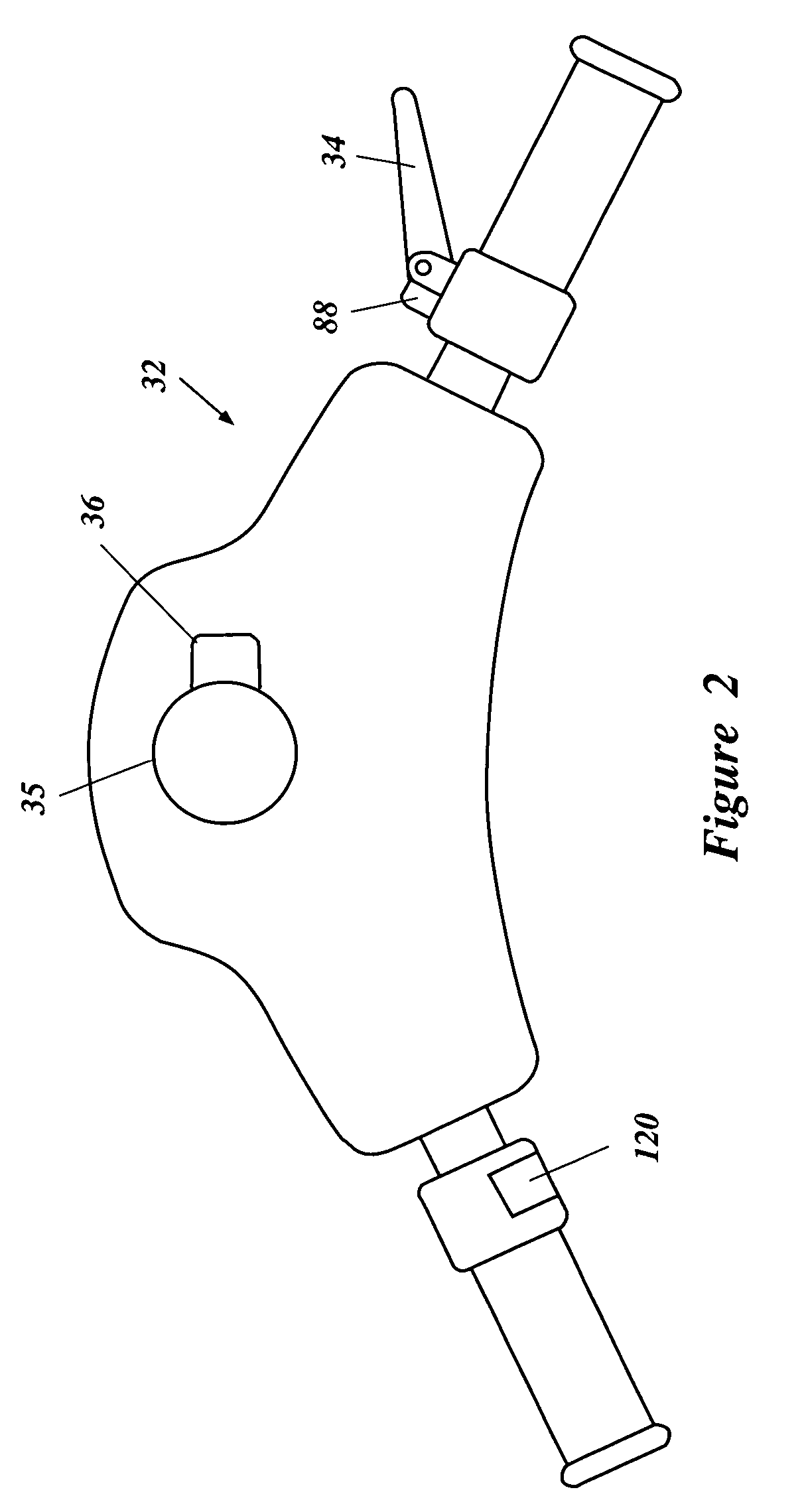
[0029]A control mast 26 extends upwardly to support a handlebar 32. The handlebar 32 is provided primarily for controlling the direction of the watercraft 10. The handlebar 32 pref...


PUM


Abstract

A control system for watercraft includes a mode switch allowing the watercraft to be operated in a number of different modes. The modes selectable by the rider can include a normal mode, a reduced output mode, a suppressed acceleration mode, an enhanced acceleration mode, and a steering mode, as well as other modes.

Description

PRIORITY INFORMATION[0001]This application is based on and claims priority to Japanese Patent Application No. 2003-173809, filed Jun. 18, 2003, the entire contents of which is hereby expressly incorporated by reference.BACKGROUND OF THE INFORMATIONS[0002]1. Field of the Inventions[0003]The present application generally relates to an engine control arrangement for controlling a watercraft, and more particularly relates to an engine management system that provides options for watercraft engine operation.[0004]2. Description of the Related Art[0005]Watercraft, including personal watercraft and jet boats, are often powered by an internal combustion engine having an output shaft arranged to drive a water propulsion device. These types of watercraft often include handlebars that are manipulated by a rider of the watercraft to effect steering. Typically, the handlebars carry a number of controls, including but without limitation, a finger or thumb-operated lever for controlling the power o...

Claims


Application Information

Patent Timeline
Patent Type & Authority Patents(United States)
IPC IPC(8): B63H21/22B63H11/08B63B35/73B63H21/21F02D9/02F02D11/10F02D41/10F02D41/12F02D41/24F02D45/00
CPCB63H21/22F02D41/2422F02D11/105B63H21/24F02D2200/604
Inventor MOTOSE, HITOSHI
Owner YAMAHA MARINE KK
Why Eureka
Try Eureka