Signal processing unit and liquid crystal display device

Inactive Publication Date: 2007-01-23
FUJITSU LTD
View PDF17 Cites 27 Cited by
  • Summary
  • Abstract
  • Description
  • Claims
  • Application Information

AI Technical Summary

Benefits of technology

[0022]According to the liquid crystal display device of the present invention, a liquid cr

Problems solved by technology

Accordingly, the above-mentioned process cannot achieve the contrast as high as the CRT display device, in the conventional liquid crystal display device.
Thus, the conventional liquid crystal display

Method used


Image

  • Signal processing unit and liquid crystal display device
  • Signal processing unit and liquid crystal display device
  • Signal processing unit and liquid crystal display device

Examples


Example

[0032]The configurations and the operations of some preferred embodiments of the present invention will be described with reference to the accompanying drawings (FIGS. 1 to 8).

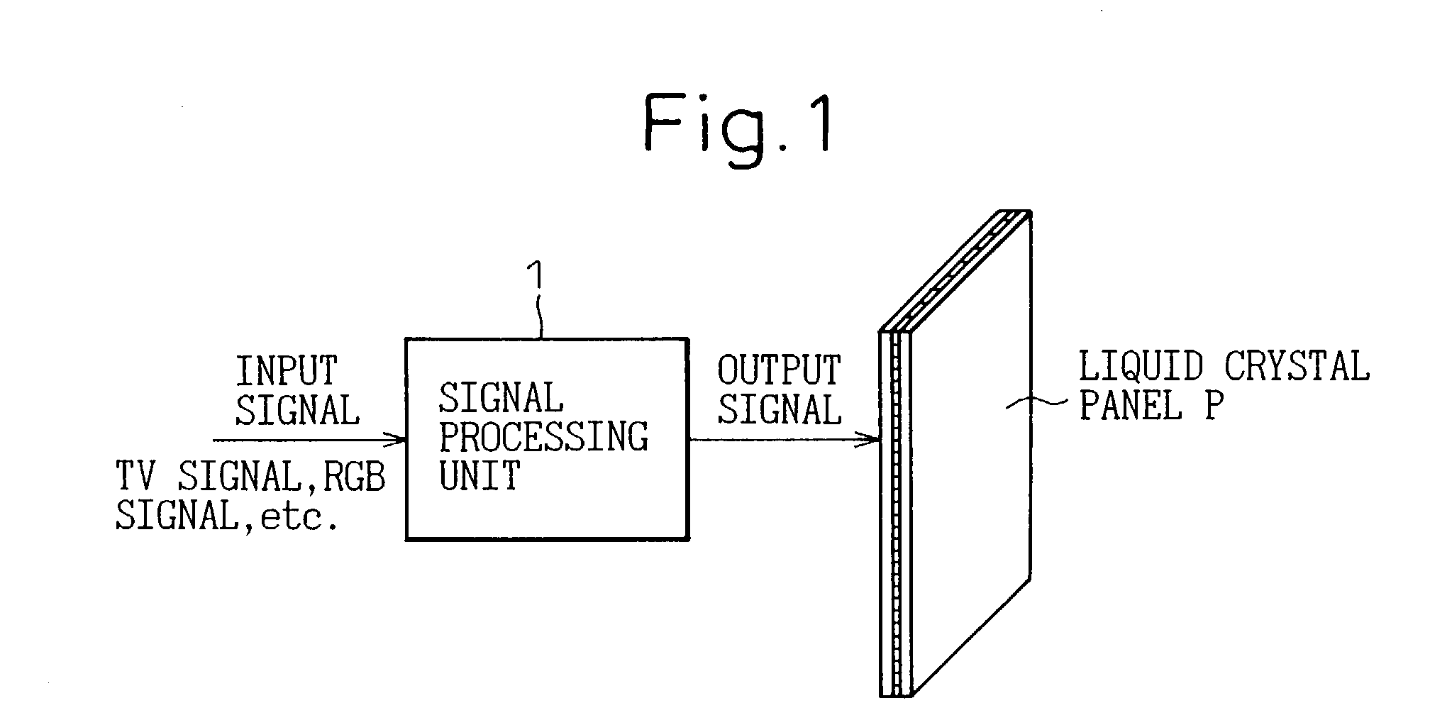
[0033]FIG. 1 is a block diagram showing a whole configuration of an embodiment of the present invention.

[0034]In FIG. 1, a video signal, such as a television signal or an RGB signal, is input into a signal processing unit as an input signal. The brightness component of the input signal is changed to be a viewable distribution for the viewer, and is output to a liquid crystal panel P as an output signal.

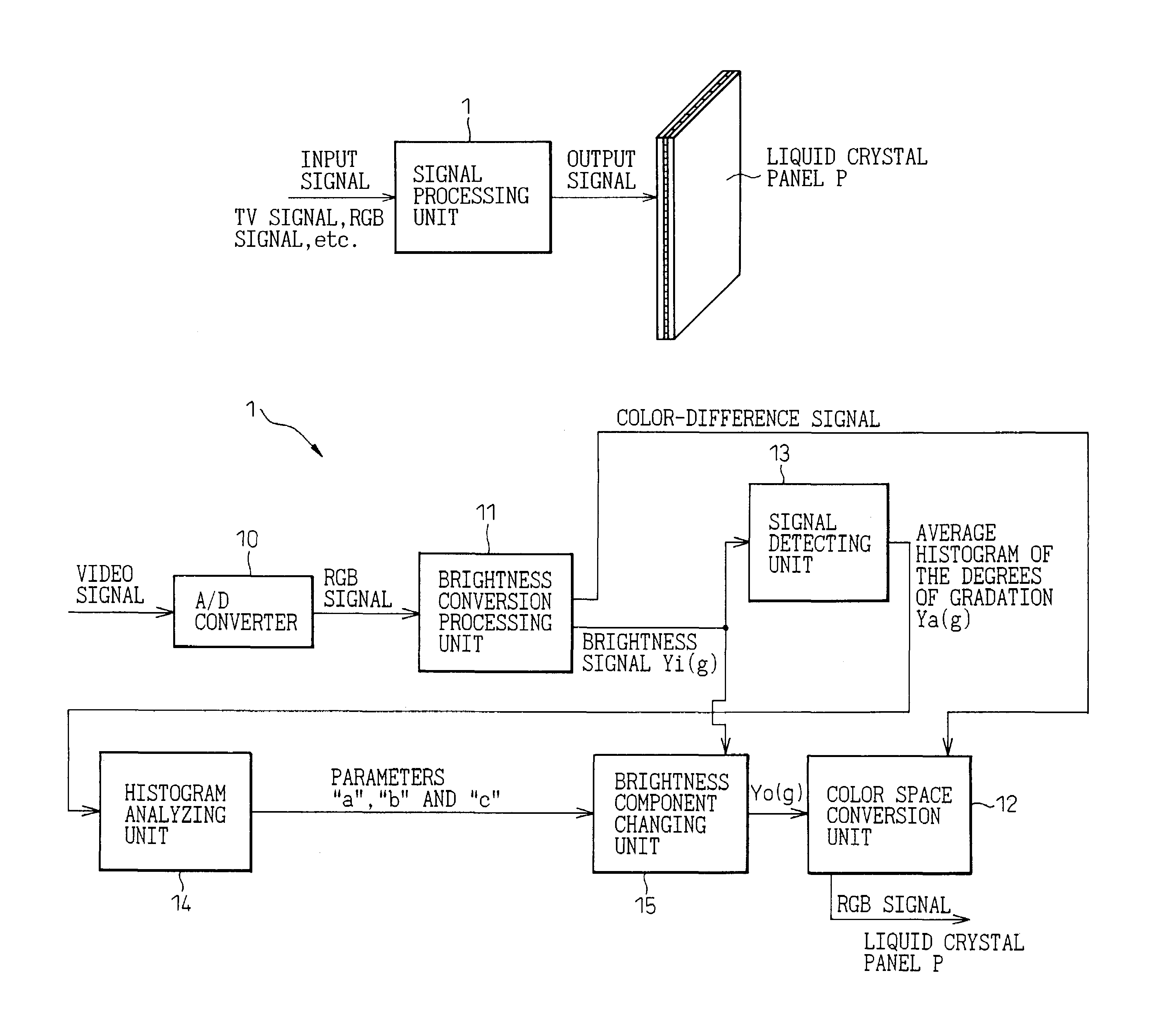
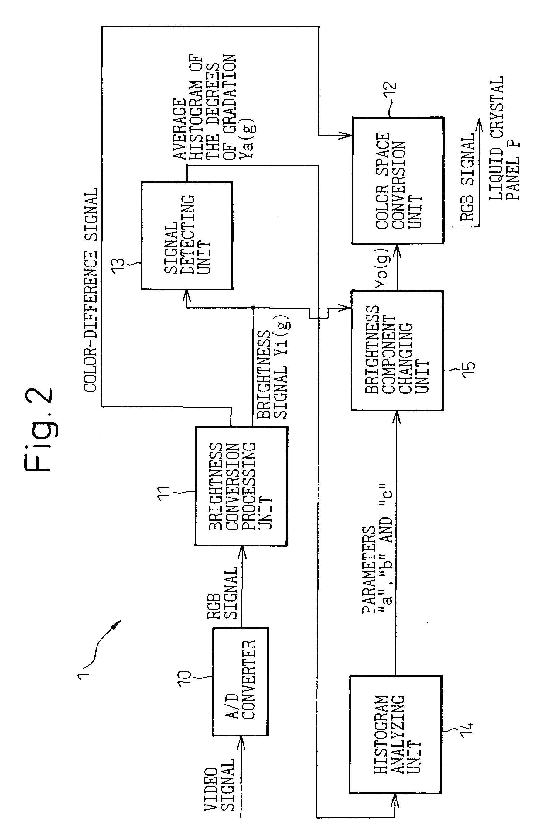
[0035]FIG. 2 is a block diagram showing a signal processing unit in the embodiment of the present invention. In this drawing, a detailed structure of the signal processing unit 1 of FIG. 1 is shown representatively. Hereinafter, the same constituent elements as mentioned before will be referred to using the same reference numerals.

[0036]In FIG. 2, the video signal is input into an AD converter (Analog to Digital...


PUM


Abstract

A signal processing unit in a liquid crystal display device, etc., includes a brightness component appearance frequency measuring unit that measures an appearance frequency of each brightness component in a video signal; a parameter outputting unit that outputs a distribution of each brightness component, as a parameter, based on the appearance frequency of each brightness component measured by the brightness component appearance frequency measuring unit; a changing signal outputting unit that alters an input signal recorded in a recording unit, by using the parameter, and that outputs the input signal as a changing signal; and a brightness component changing unit that changes a distribution of each brightness component, by using the changing signal, and that outputs the video signal in which the distribution of each brightness component is changed.

Description

BACKGROUND OF THE INVENTION[0001]1. Field of the Invention[0002]The present invention relates to a liquid crystal display device. In particular, the present invention relates to a liquid crystal display device, to which a television signal for a television apparatus with NTSC (National Television System Committee), PAL (Phase Alternation by Line), HDTV (High Definition Television), or the like, and an RGB (Red, Green and Blue) signal for a personal computer, can be input.[0003]2. Description of the Related Art[0004]There are CRT (Cathode Ray Tube) display device and a liquid crystal display device for displaying moving pictures of a television apparatus or the like.[0005]A CRT display device is a self-luminous analog device comprised of a fluorescent phosphor which emits light spontaneously when electrons collide with the phosphor.[0006]Not to brighten or darken a screen unnecessarily, a CRT display device carries out the following process; namely, the CRT display device keeps suffi...

Claims


Application Information

Patent Timeline
IPC IPC(8): H04N5/14G06K9/00G09G5/00H04N5/202H04N9/74G02F1/133G09G3/20G09G3/34G09G3/36H04N5/57H04N5/66
CPCG09G3/3413G09G3/3611H04N21/44008H04N5/57H04N21/4318G09G2320/0626G09G2320/0646G09G2320/0673G09G2360/16G09G2320/066
Inventor HIROSUE, YOJI
Owner FUJITSU LTD
Why Eureka
Try Eureka