Full range loudspeaker

Inactive Publication Date: 2007-01-23
HARMAN INT IND INC
View PDF32 Cites 39 Cited by
  • Summary
  • Abstract
  • Description
  • Claims
  • Application Information

AI Technical Summary

Benefits of technology

[0012]The loudspeaker driver of the invention is designed so that the suspension system of the driver is connected to the voice coil former rather than to the diaphragm. In particular, the edge-driven voice coil/diaphragm assembly is supported by a single surround suspension member attached to the tubular voice coil former in a location spaced at a predetermined distance from the point at which the voice coil former attac

Problems solved by technology

One common problem with smaller sized loudspeakers is as the size of the loudspeakers becomes smaller, achieving acceptable low frequency response becomes more difficult.
Since smaller loudspeakers have a smaller diaphragm and stiffer suspension, the volume displacement, and thus the performance, is limited by the ability to manufacture loudspeakers with very low stiffness and high excursion capabilities.
A general problem with the current construction of edge-driven speakers is the difficulty of precisely aligning the components during manufacturing, as the magnetic air gap is shielded by the diaphragm.
This forces the removal of all alignment gauges prior t

Method used


Image

  • Full range loudspeaker
  • Full range loudspeaker
  • Full range loudspeaker

Examples


Embodiment Construction

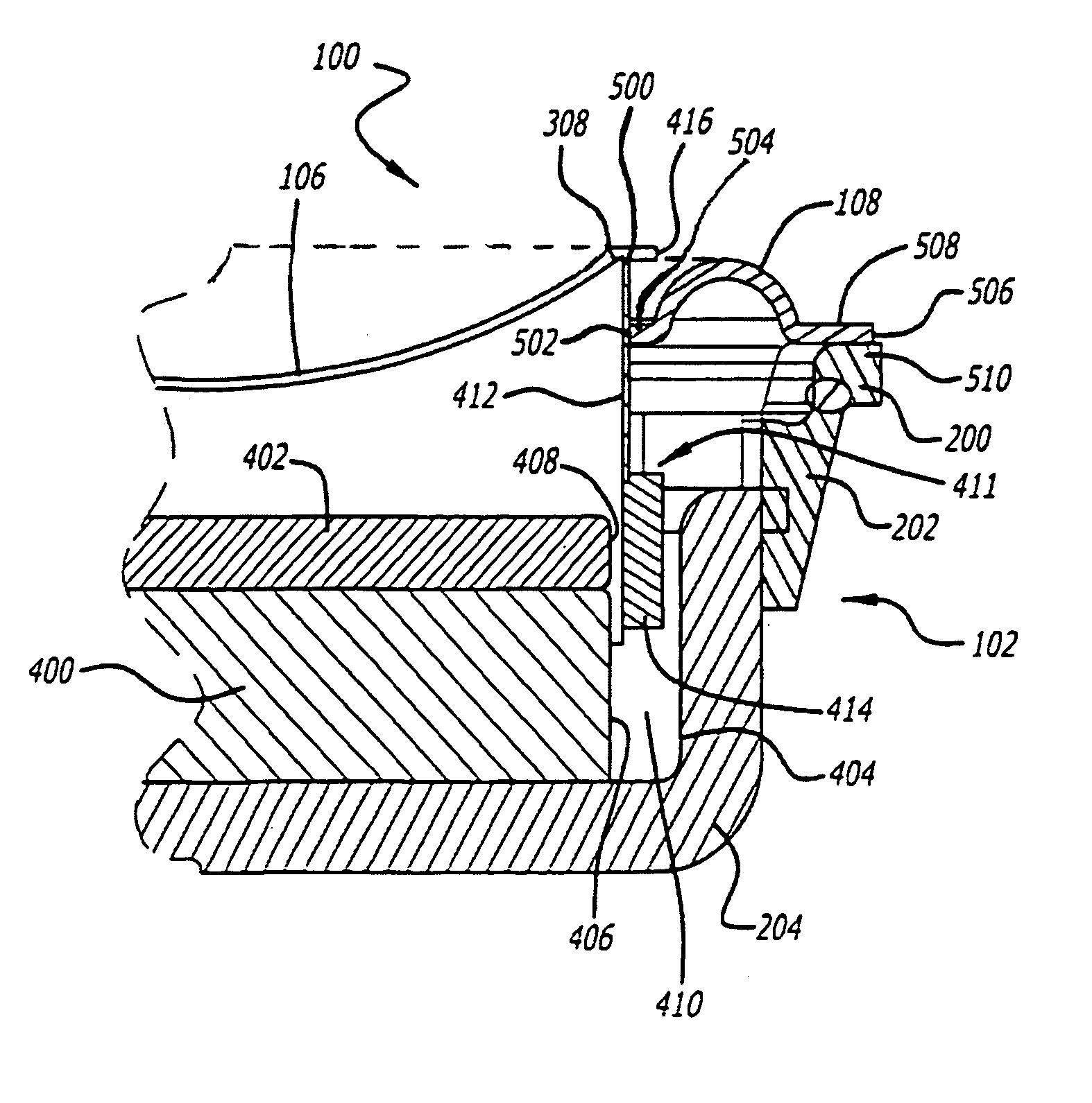
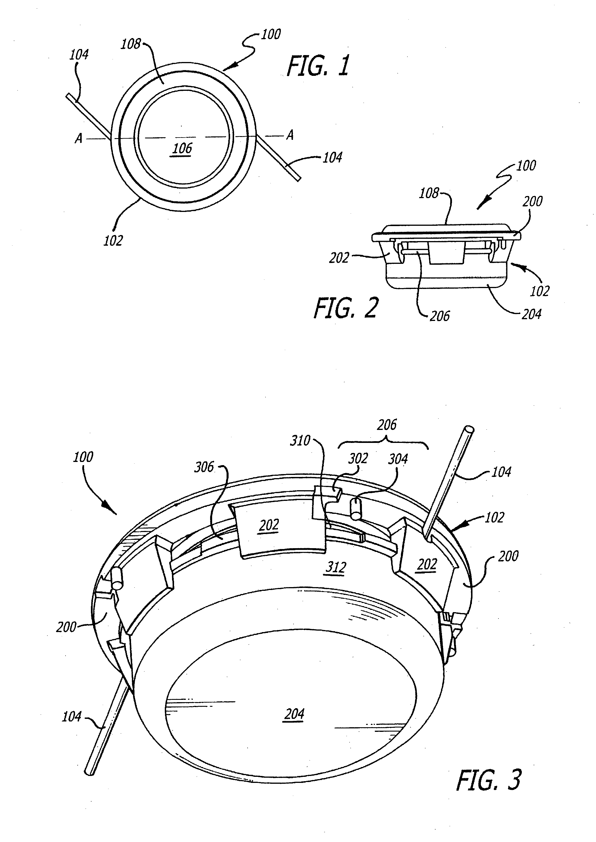
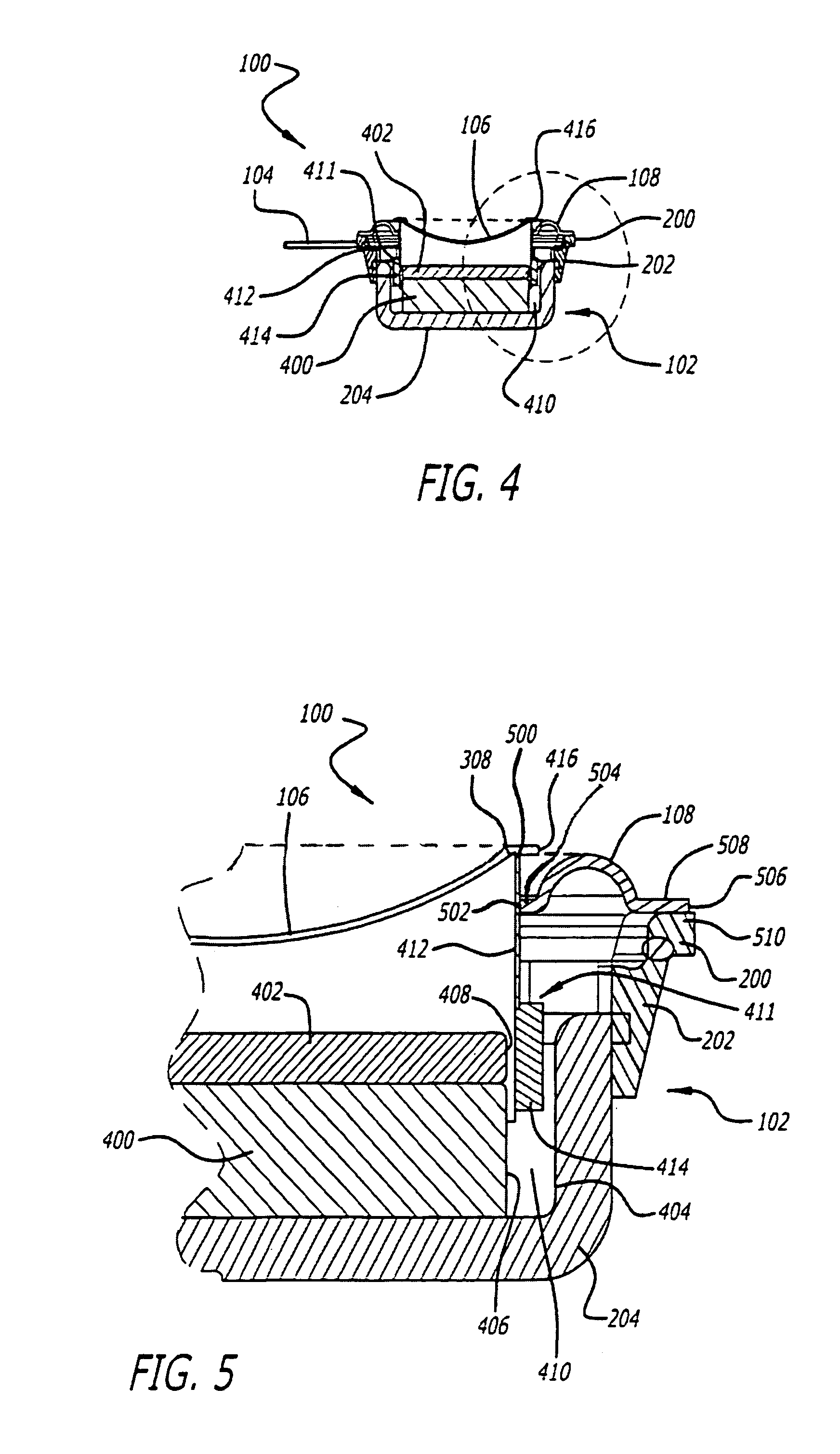
[0022]FIG. 1 is a front view of an edge-driven diaphragm loudspeaker driver 100 of the invention. The loudspeaker driver 100 has a frame 102 defining a circular perimeter. A pair of hookup wires 104 are shown extending outwardly from the frame 102. Also illustrated is the diaphragm 106 and a surround member 108 positioned within the frame 102 of the loudspeaker driver 100. The construction of the diaphragm 106 and the surround member 108 within the frame 102 are further explained below.

[0023]FIG. 2 is a side view of the loudspeaker driver 100 of FIG. 1 and illustrates the surround suspension member 108 extending upwardly from the frame 102 of the loudspeaker driver 100. FIG. 2 also illustrates the frame 102 of the loudspeaker driver 100 formed from a mounting ring 200, a polar array of buttress blocks 202 and a pot 204. The pot 204 of the frame 102 is a cupped shaped member that is engaged by the mounting ring 200, through the use of the buttress blocks 202. The mounting ring 200 is...


PUM


Abstract

An edge-driven diaphragm loudspeaker driver is configured such that the suspension system of the driver is connected to the voice coil rather than to the diaphragm. Thus, the diaphragm in the loudspeaker is free of suspension systems connected to or extending from the diaphragm. By attaching the surround suspension to the voice coil rather than to the diaphragm, the diaphragm is isolated from the influence of spurious high frequency vibrations in the suspension system, thereby increasing the performance of the loudspeaker at high frequencies. The loudspeaker driver configuration also provides for a longer excursion range for the voice coil/diaphragm assembly, which allows for the driver components to be more accurately aligned during manufacturing, thereby enabling the loudspeaker driver to operate as a full range unit by producing low output frequencies.

Description

CROSS REFERENCE TO RELATED APPLICATIONS[0001]This application claims priority of U.S. provisional application Ser. No. 60 / 093,600 filed Jul. 21, 1998 and U.S. application Ser. No. 09 / 346,954, filed Jul. 1, 1999, both incorporated by reference into this application.BACKGROUND OF THE INVENTION[0002]1. Field of Invention[0003]The invention relates to the field of loudspeakers and more particularly to the configuration of a loudspeaker driver suspension system.[0004]2. Related Art[0005]The general construction of a loudspeaker driver consists of a diaphragm, voice coil, magnetic motor, frame and suspension system. The magnetic motor is generally attached to the frame. The voice coil and diaphragm are then mounted to the frame via the suspension system, which may include one or more suspension members. The voice coil of the driver typically consists of a voice coil former having a wire wound about the lower portion of the voice coil former. Often times, although not necessary, the voice ...

Claims


Application Information

Patent Timeline
IPC IPC(8): H04R1/00H04R11/02H04R9/06H04R1/20H04R9/04H04R7/20H04R9/02
CPCH04R9/06H04R9/00
Inventor WILLIAMSON, CLAYTON C.
Owner HARMAN INT IND INC
Why Eureka
Try Eureka