
System and method for engine operation with spark assisted compression ignition

a technology of compression ignition and engine, applied in the direction of machines/engines, electric control, combustion air/fuel air treatment, etc., can solve the problems of increasing emissions, affecting the timing of combustion, and affecting the efficiency of combustion, so as to reduce fuel consumption, improve performance, and increase emissions

Active Publication Date: 2007-01-30
FORD GLOBAL TECH LLC
View PDF23 Cites 49 Cited by
  • Summary
  • Abstract
  • Description
  • Claims
  • Application Information

AI Technical Summary

Benefits of technology

[0003]The inventors herein have recognized that one issue with such autoignition-type operation is that the timing of combustion can be affected by many parameters. For example, the timing of combustion may be affected by charge temperature, air-fuel ratio, engine speed, and / or engine load. Specifically, small variations in such parameters can result in auto-ignition occurring too early, or too late. Such variation can increase emissions and reduce fuel savings, thereby degrading performance.
[0004]As such, the inventors herein have also recognized that, when trying to purge fuel vapors into the engine, one particular way in which combustion timing may be inadvertently affected is due to uncertainty in the concentration and / or amount of fuel vapors being purged into the combustion chamber. In other words, during fuel vapor purging operations, recycled fuel vapors may substantially increase the variability of fuel temperature, atomization and / or air-fuel ratio, thus exacerbating degradation of ignition timing control. One approach is to avoid fuel vapor purging during auto-ignition operation, and discontinue such operation when it is necessary to purge fuel vapors; however, this can limit the available time to operating with auto-ignition.
[0006]In this way, it is possible, during at least some periods of fuel vapor purging, to utilize a spark-assisted autoignition, and thereby still maintain accurate control of combustion timing while also purging fuel vapors. Thus, additional auto-ignition operation can be realized, while still providing sufficient opportunity to purge fuel vapors. Note that spark-assisted auto-ignition may be used without fuel vapor purging as well, if desired.

Problems solved by technology

The inventors herein have recognized that one issue with such autoignition-type operation is that the timing of combustion can be affected by many parameters.
Specifically, small variations in such parameters can result in auto-ignition occurring too early, or too late.
Such variation can increase emissions and reduce fuel savings, thereby degrading performance.
In other words, during fuel vapor purging operations, recycled fuel vapors may substantially increase the variability of fuel temperature, atomization and / or air-fuel ratio, thus exacerbating degradation of ignition timing control.
One approach is to avoid fuel vapor purging during auto-ignition operation, and discontinue such operation when it is necessary to purge fuel vapors; however, this can limit the available time to operating with auto-ignition.

Method used


Image

  • System and method for engine operation with spark assisted compression ignition
  • System and method for engine operation with spark assisted compression ignition
  • System and method for engine operation with spark assisted compression ignition

Examples


Embodiment Construction

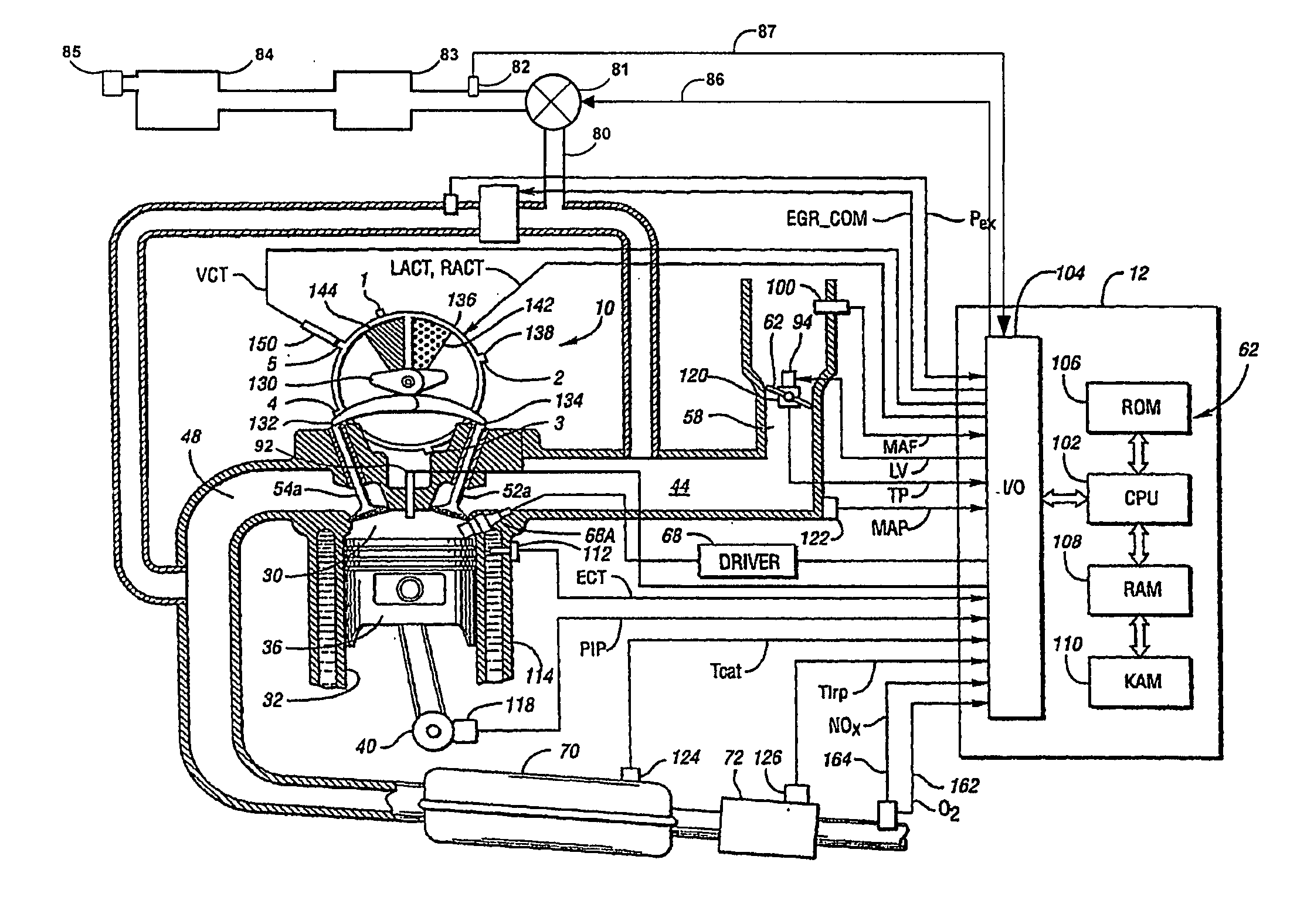
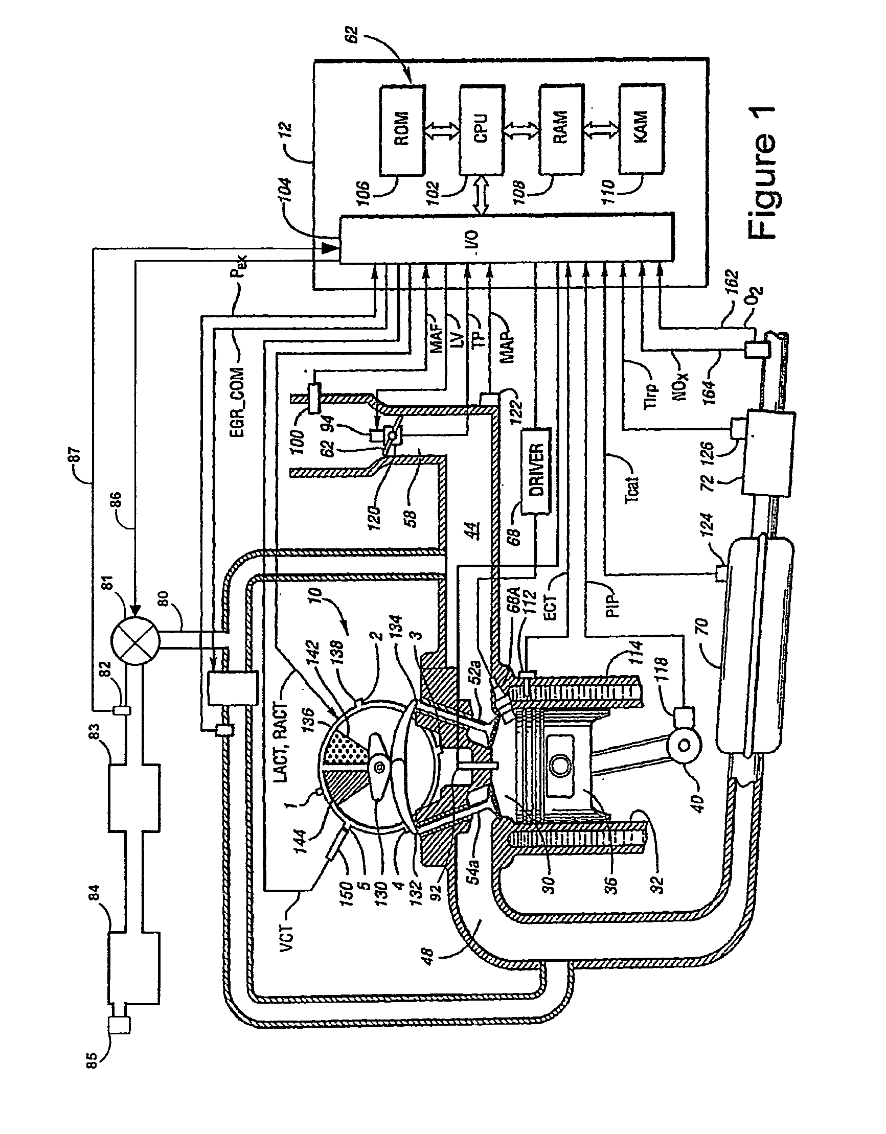
[0014]Direct injection spark ignited internal combustion engine 10, comprising a plurality of combustion chambers, is controlled by electronic engine controller 12 as shown in FIG. 1. Combustion chamber 30 of engine 10 includes combustion chamber walls 32 with piston 36 positioned therein and connected to crankshaft 40. In one example, piston 36 includes a recess or bowl (not shown) to form selected levels of stratification or homogenization of charges of air and fuel. Alternatively, a flat piston may also be used.

[0015]Combustion chamber 30 is shown communicating with intake manifold 44 and exhaust manifold 48 via respective intake valves 52a and 52b (not shown), and exhaust valves 54a and 54b (not shown). Fuel injector 66 is shown directly coupled to combustion chamber 30 for delivering liquid fuel directly therein in proportion to the pulse width of signal fpw received from controller 12 via conventional electronic driver 68. Fuel is delivered to fuel system (not shown) including...


PUM


Abstract

A method of operating an internal combustion engine having a combustion chamber with a piston, comprising: inducting at least air and fuel vapors from a fuel vapor system; and adjusting an operating condition of the engine so that a mixture of air and fuel in the combustion chamber, including said fuel vapor, approaches, but does not achieve, said autoignition temperature; and performing a spark from the spark plug so that said mixture substantially auto-ignites.

Description

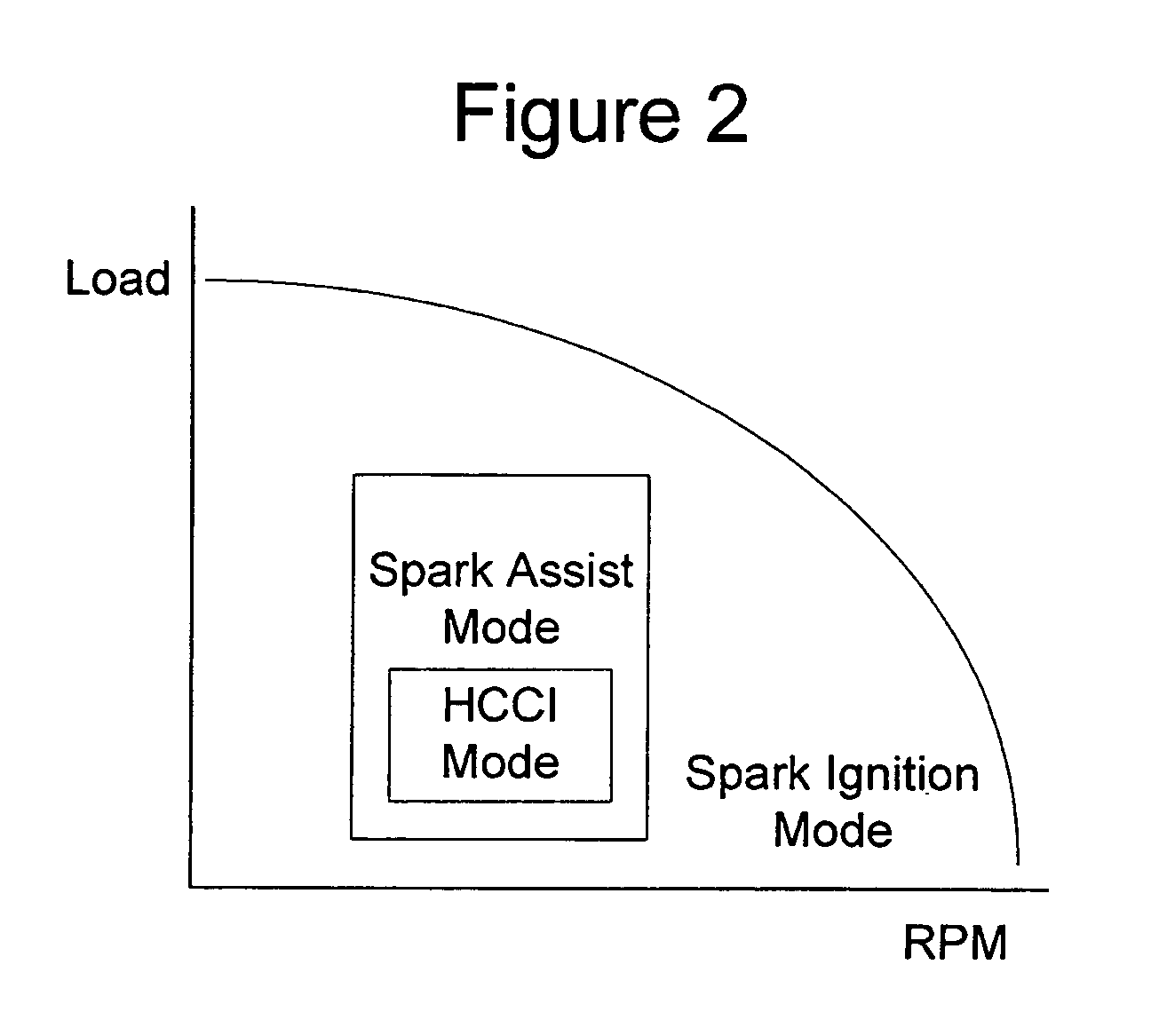
FIELD[0001]The present application relates to controlling engine operation during various combustion modes.BACKGROUND AND SUMMARY[0002]Various types of combustion may be used in an internal combustion engine. For example, spark ignition (SI) of a homogenous mixture during the expansion stroke is one example method. This method relies on a timed spark from a sparking plug in order to achieve ignition within the combustion chamber of an air and fuel mixture. Another type of combustion may be referred to as homogeneous charge compression ignition (HCCI), which occurs when the temperature of the combustion chamber exceeds the required conditions for the specific fuel resulting in autoignition. HCCI can be used to provide greater fuel efficiency and reduced NOx production under some conditions. One example of such operation is described in U.S. Pat. No. 6,390,054.[0003]The inventors herein have recognized that one issue with such autoignition-type operation is that the timing of combusti...

Claims


Application Information

Patent Timeline
IPC IPC(8): F02M25/07F02B17/00
CPCF02D41/003F02D41/3041F02B1/12F02B23/104F02B29/0418F02B2075/125F02D13/0207F02D41/3064F02D41/3076F02M25/089F02M31/042Y02T10/123F02D41/0057Y02T10/12
Inventor YANG, JIALIN
Owner FORD GLOBAL TECH LLC
Learn More