Motor-operated valve apparatus

a technology of motor-operated valves and valve bodies, which is applied in the direction of dynamo-electric converter control, gaseous heating fuel, stoves or ranges, etc., can solve the problems of short time period over which the disorder occurs, and achieve the effect of short time, quick ignition and effective prevention of user annoyan

Inactive Publication Date: 2007-01-30
RINNAI CORP
View PDF8 Cites 18 Cited by
  • Summary
  • Abstract
  • Description
  • Claims
  • Application Information

AI Technical Summary

Benefits of technology

[0013]According to the motor-operated valve apparatus of the present invention, the flow control valve is displaced to the predetermined position closer to the first end of both ends of the motion thereof when the fluid channel is interrupted (when an on-off valve provided in the fluid channel aside from the flow control valve is closed) while the motor drive circuit and control means receive electric source power. Thus, the flow control valve is displaced to the predetermined position closer to the first end when the supply of electric source power is restarted after the supply of the electric source power to the motor drive circuit and control means is stopped. In this state, a predetermined number of pulses capable of displacing the flow control valve from the first end to the second end being the home position are supplied to the motor to displace the flow control valve to the home position. In this case, the initial position of the flow control valve is the position closer to the first end, and therefore the number of pulses supplied to the stepping motor (the predetermined number of pulses) is larger than the number of pulses required for displacing the flow control valve from its initial position to the home position (second end), but the extra number is sufficiently small. That is, the number of pulses supplied to the stepping motor by the shift-to-home position controlling means is slightly larger than a minimum necessary number of pulses for the entire motion range of the flow control valve (range from the first end to the second end) (the minimum necessary number of pulses plus the number of pulses sufficiently smaller than the minimum necessary number of pulses), and the number of pulses is slightly larger than a minimum necessary number of pulses required for displacing the flow control valve from the initial position closer to the first end to the home position (second end). As a result, when a predetermined number of pulses are supplied to the stepping motor by the shift-to-home position controlling means, the flow control valve is mechanically restrained to the home position before the supply of the pulses, but thereafter the supply of pulses is completed in short time. That is, when the flow control valve is shifted to the home position, a disorder of the stepping motor occurs just before completion of the shift, but the time period over which the disorder occurs is sufficiently short.
[0014]Thus, according to the present invention, the flow control valve can be shifted to the home position while preventing occurrence of the disorder of the stepping motor, abnormal sounds and vibrations wherever possible in a simple configuration without requiring means for detecting arrival of the flow control valve at the home position.
[0017]The present invention is suitable if the flow control valve is a thermal power control valve provided in a channel for suppying gas to a burner of a gas cooking appliance for controlling a flow of the gas to the burner. That is, since the gas cooking appliance is placed in a room, and a user works near the gas cooking appliance, abnormal sounds and vibrations during occurrence of the disorder of the stepping motor tends to annoy the user if they continue for a long time period. Nevertheless, according to the present invention, the disorder of the stepping motor occurs only for a very short time period as described previously, thus making it possible to effectively prevent such inconvenience at a low cost.
[0019]Hence, the predetermined position closer to the first end is the position close to the position predetermined as the displacement position of the thermal power control valve when the burner is ignited. Thus, when an instruction to ignite the burner is provided while the electric source power to the motor drive circuit and control means after the thermal power control valve is displaced to the predetermined position closer to the first end by the motor standby operation controlling means, the thermal power control valve can be displaced to the displacement for ignition by the stepping motor quickly (in short time). Therefore, the burner can be ignited quickly. The predetermined position closer to the first end may be identical to the ignition position.
[0020]The present invention applied to the gas cooking appliance as described above is suitable when the gas cooking appliance comprises a plurality of sets of the burner, thermal power control valve, stepping motor and motor drive circuit. That is, if the gas cooking appliance comprises a plurality of sets of the burner, thermal power control valve, stepping motor and motor drive circuit, it is necessary to display thermal power control valves to the home position by stepping motors corresponding to the respective thermal power control valves when electric source power is supplied to the motor drive circuit and control means, and therefore if the disorder occurs for a relatively long time period with a plurality of stepping motors, the user tends to be annoyed badly. Nevertheless, according to the present invention, the time period over which the disorder occurs with stepping motors is sufficiently short, and therefore annoyance of the user is effectively prevented. Means for detecting arrival of the thermal power control valve at the home position is not required for any stepping motors, and therefore the cost advantage is significant.

Problems solved by technology

That is, when the flow control valve is shifted to the home position, a disorder of the stepping motor occurs just before completion of the shift, but the time period over which the disorder occurs is sufficiently short.

Method used


Image

  • Motor-operated valve apparatus
  • Motor-operated valve apparatus
  • Motor-operated valve apparatus

Examples


Embodiment Construction

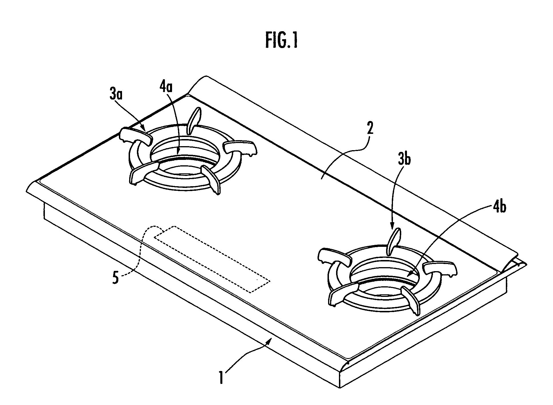
[0029]One embodiment of the present invention will be described with reference to FIGS. 1 to 8. This embodiment is an example where the present invention is applied to a gas cooking appliance.

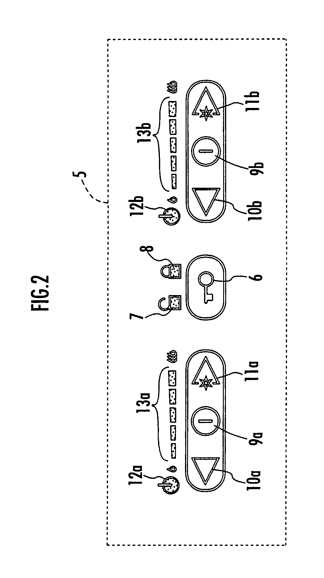
[0030]FIG. 1 is an outline perspective view of a gas cooking appliance 1, and FIG. 2 is a plan view of an operation / display portion of the gas cooking appliance 1. Referring to these drawings, the gas cooking appliance 1 comprises burners 4a, 4b below two trivets 3a, 3b placed in a top plate 2 of the gas cooking appliance 1, respectively, in this embodiment. An operation / display portion 5 is provided at a center of the top plate 2 on the front side. The operation / display portion 5 comprises a switch 6 and display lamps 7, 8 associated with actuation of the entire gas cooking appliance 1, switches 9a, 10a, 11a and display lamps 12a, 13a associated with actuation of the burner 4a, and switches 9b, 10b, 11b and display lamps 12b, 13b associated with actuation of the burner 4b. In this embodiment, ...


PUM


Abstract

When a fluid flow channel is interrupted while an electronic circuit unit 50 including a microcomputer 51 and the like receives electric source power, a flow control valve is displaced to a predetermined position closer to a first end of both ends of a motion range of the flow control valve in the fluid flow channel by a stepping motor 29. When the supply of electric source power is restarted after the supply of electric source power to the electronic circuit unit 50 is stopped, a predetermined number of pulses capable of displacing the flow control valve from the first end to a home position are supplied to the stepping motor 29 to displace the flow control valve to the home position with a second end of both ends of the motion range of the flow control valve being the home position of the flow control valve. Thus, the flow control valve is shifted to the home position while preventing occurrence of a disorder of the stepping motor, abnormal sounds and vibrations, in a simple configuration, without requiring means for detecting arrival of the flow control valve at the home position.

Description

BACKGROUND OF THE INVENTION[0001]1. Field of the Invention[0002]The present invention relates to a motor-operated valve apparatus driving a flow control valve such as a thermal power control valve of a gas cooking appliance by a stepping motor.[0003]2. Description of the Related Art[0004]In a motor-operated valve apparatus operating a flow control valve using a stepping motor as an actuator, the amount of displacement of the flow control valve matches the number of pulses supplied to the stepping motor (hereinafter referred to simply as motor in this section). That is, the amount of rotation of the motor per pulse is fixed and accordingly, the amount of displacement (amount of change in opening degree) of the flow control valve per pulse is fixed. In this motor-operated valve apparatus, the number of pulses supplied to the motor defines a relative amount of change in opening degree of the flow control valve, and therefore for controlling the opening degree (displacement position) of...

Claims


Application Information

Patent Timeline
Patent Type & Authority Patents(United States)
IPC IPC(8): F16K31/44F16K3/08F16K31/04F16K37/00F23K5/00F24C3/12G05D7/06H02P8/00
CPCF16K3/085F16K31/041G05D7/0635F24C3/124F24C3/126F16K31/046B31B50/006B31B50/78
Inventor GAMA, ATSUHITOHATA, SHINICHIROYAMADA, HIROYUKIHIROTA, KAZUYA
Owner RINNAI CORP
Why Eureka
Try Eureka