Vehicular brake system and method of controlling same brake system

a brake system and brake system technology, applied in the direction of braking systems, analogue processes for specific applications, instruments, etc., can solve the problems of sometimes decreasing braking force, and achieve the effect of reducing braking force, allowing steering operation during braking, and stabilizing vehicle behavior

Active Publication Date: 2007-01-30
TOYOTA JIDOSHA KK +1
View PDF23 Cites 10 Cited by
  • Summary
  • Abstract
  • Description
  • Claims
  • Application Information

AI Technical Summary

Benefits of technology

[0014]According to the above-described brake system, during the specific brake control mode, the wheel is prevented from being locked and the steering operation during braking is allowed. Furthermore, the actual yaw rate of the vehicle is controlled to the target yaw rate, thereby stabilizing the vehicle behavior with respect to the yaw direction. If the braking force of the wheel is expected to reduce, the reduction in the braking force is curbed by ensuring through an adjustment of the target slip rate, a provision of a greater longitudinal force on the wheel than that obtained with the target slip rate determined or would have been determined by the first correction.

Problems solved by technology

However, in the related-art brake systems, the braking force may sometimes decrease depending on the road surface condition during the ABS control.

Method used


Image

  • Vehicular brake system and method of controlling same brake system
  • Vehicular brake system and method of controlling same brake system
  • Vehicular brake system and method of controlling same brake system

Examples


Embodiment Construction

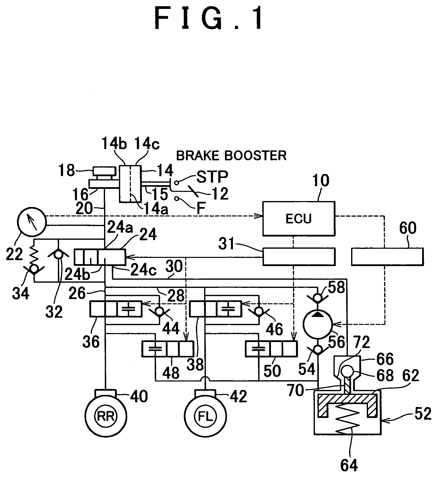
[0023]Preferred embodiments of the invention will be described hereinafter with reference to the accompanying drawings. Like components and portions are represented by like reference numerals, and will not be redundantly described below. FIG. 1 is a diagram illustrating the construction of a brake system in accordance with one embodiment of the invention.

[0024]The brake system of the embodiment is a hydraulic brake apparatus, and is controlled by an electronic control unit (hereinafter, referred to as “ECU”) 10. FIG. 1 shows component elements constituting brake mechanisms for a front left wheel FL and a rear right wheel RR. A brake hydraulic system will first be described.

[0025]A braking force control apparatus includes a brake pedal 12. The brake pedal 12 is connected to an actuation shaft 15 of a brake booster 14. A master cylinder 16 is fixed to the brake booster 14. In the brake booster 14 are a constant pressure chamber 14b and a variable pressure chamber 14c that are partiall...


PUM


Abstract

The brake system of the invention, during the ABS control mode, corrects the target slip rate in accordance with the turning of the vehicle, and determines whether the vehicle is running on a poor surface road. If the vehicle is running on a poor surface road, the system sets a target slip rate that provides a greater longitudinal force than the aforementioned target slip rate.

Description

INCORPORATION BY REFERENCE[0001]The disclosure of Japanese Patent Application No. 2002-381319 filed on Dec. 27, 2002, including the specification, drawings and abstract is incorporated herein by reference in its entirety.BACKGROUND OF THE INVENTION[0002]1. Field of the Invention[0003]The invention relates to a brake system and a method of controlling the same brake system.[0004]2. Description of the Related Art[0005]An anti-skid (anti-lock) brake system (ABS) prevents a wheel from locking during hard braking and allows a steering operation during hard braking, and is a known as an active safety apparatus.[0006]The following brake systems are known.[0007](1) A system in which an anti-lock control is changed in accordance with an index that indicates the momentum of a running vehicle (see Japanese Patent Application Laid-Open Publication No. 10-6968).[0008](2) A system in which a physical quantity that indicates the state of run of a vehicle is taken into account in determination of a...

Claims


Application Information

Patent Timeline
Patent Type & Authority Patents(United States)
IPC IPC(8): B60T8/24B60T8/1755B60T8/1764B60T8/58B60T8/88
CPCB60T8/1755B60T8/1764B60T8/885B60T2210/16B60T2210/14
Inventor NIHEI, TOSHIHISAHARA, MASAHIROMATSUURA, MASAHIRODOURA, AKIFUMI
Owner TOYOTA JIDOSHA KK
Why Eureka
Try Eureka