Gas distribution system with tuning gas

a technology of gas distribution system and tuning gas, which is applied in the direction of coating, chemical vapor deposition coating, metallic material coating process, etc., can solve the problems of high cost and complex design

Inactive Publication Date: 2007-01-30
LAM RES CORP
View PDF88 Cites 43 Cited by
  • Summary
  • Abstract
  • Description
  • Claims
  • Application Information

AI Technical Summary

Benefits of technology

[0010]In another embodiment, a tuning system for tuning a gas feed system for a processing chamber with a controller, where the gas feed system comprises a first leg for supplying a processing gas to a first part of the processing chamber, a second leg for supplying the processing gas to a second part of the processing chamber, and a flow ratio device for maintaining a flow ratio between the first leg and the second leg is provided. A first gas line in fluid connection with the first leg is provided. A second gas line in fluid connection with the second leg is provided. A tuning gas source in fluid connection with the first gas line and the second gas line is provided. A mass flow controller connected between the first gas line and the tuning gas source is provided.

Problems solved by technology

However, these gas distribution designs require numerous components, complexity in design and high cost.

Method used


Image

  • Gas distribution system with tuning gas
  • Gas distribution system with tuning gas
  • Gas distribution system with tuning gas

Examples


Embodiment Construction

[0017]The present invention will now be described in detail with reference to a few preferred embodiments thereof as illustrated in the accompanying drawings. In the following description, numerous specific details are set forth in order to provide a thorough understanding of the present invention. It will be apparent, however, to one skilled in the art, that the present invention may be practiced without some or all of these specific details. In other instances, well known process steps and / or structures have not been described in detail in order to not unnecessarily obscure the present invention.

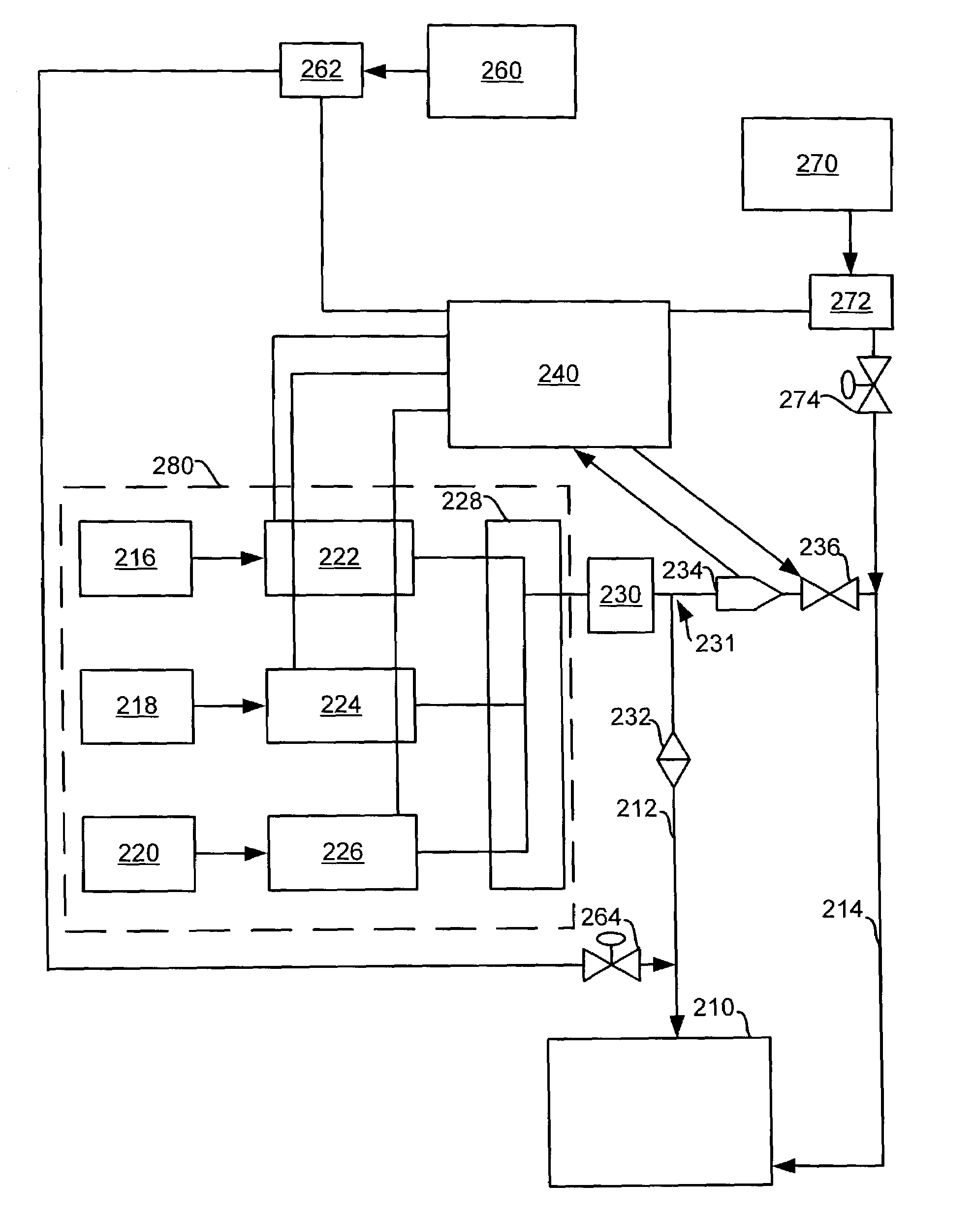
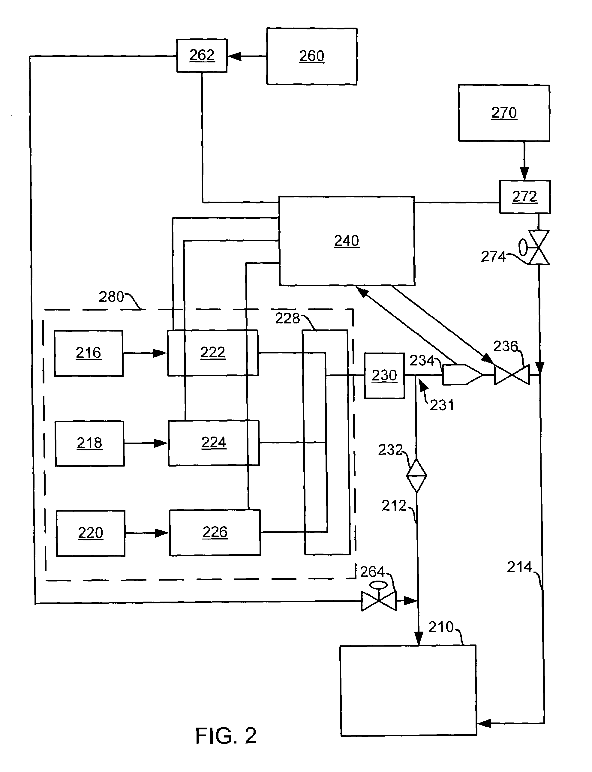
[0018]FIG. 2 is a schematic illustration of an embodiment of the invention. A processing chamber 210 is supplied processing gas through gas supply line 212 (which can provide process gas to a showerhead or other gas supply arrangement arranged in the upper portion of the chamber) and a gas supply line 214 (which supplies processing gas to a lower portion of the chamber such as, for example...


PUM

PropertyMeasurementUnit
sizesaaaaaaaaaa
sizesaaaaaaaaaa
flow resistanceaaaaaaaaaa

Abstract

An apparatus for providing different gases to different zones of a processing chamber is provided. A gas supply for providing an etching gas flow is provided. A flow splitter in fluid connection with the gas supply for splitting the etching gas flow from the gas supply into a plurality of legs is provided. A tuning gas system in fluid connection to at least one of the legs of the plurality of legs is provided.

Description

BACKGROUND OF THE INVENTION[0001]Semiconductor processing includes deposition processes such as chemical vapor deposition (CVD) of metal, dielectric and semiconducting materials, etching of such layers, ashing of photoresist masking layers, etc. Such semiconductor processes are typically carried out in vacuum chambers wherein process gas is used to treat a substrate such as a semiconductor wafer, flat panel display substrate, etc. The process gas can be supplied to the interior of the vacuum chamber by a gas distribution system such as a showerhead, a gas distribution ring, gas injectors, etc. Reactors having plural gas distribution systems are disclosed in U.S. Pat. Nos. 5,134,965; 5,415,728; 5,522,934; 5,614,055; 5,772,771; 6,013,155; and 6,042,687.[0002]In the case of etching, plasma etching is conventionally used to etch metal, dielectric and semiconducting materials. A plasma etch reactor typically includes a pedestal supporting the silicon wafer on a bottom electrode, an energ...

Claims


Application Information

Patent Timeline
Patent Type & Authority Patents(United States)
IPC IPC(8): C23C16/52C23C16/00C23C16/455H01L21/306H01L21/00
CPCH01L21/67017
Inventor LARSON, DEAN J.KADKHODAYAN, BABAKWU, DITAKESHITA, KENJIYEN, BI-MINGSU, XINGCAIDENTY, JR., WILLIAM M.LOEWENHARDT, PETER
Owner LAM RES CORP
Why Eureka
Try Eureka