
Precalendering method, finishing method and apparatus for implementing the methods

a technology of finishing method and method, applied in the field of precalendering method, can solve problems such as one-sided quality and runnability

Inactive Publication Date: 2007-01-30
VALMET TECH INC
View PDF14 Cites 0 Cited by
  • Summary
  • Abstract
  • Description
  • Claims
  • Application Information

AI Technical Summary

Benefits of technology

[0011]The purpose of the invention is to present a solution for the above-mentioned drawbacks and to introduce a precalendering method by means of which it is possible to improve the runnability of the web in the film transfer coating process following thereafter without impairing the quality.
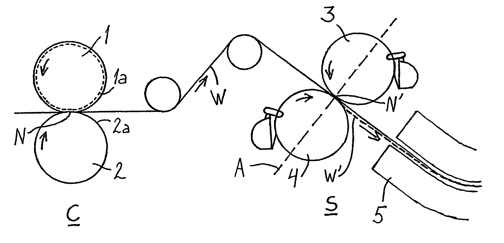
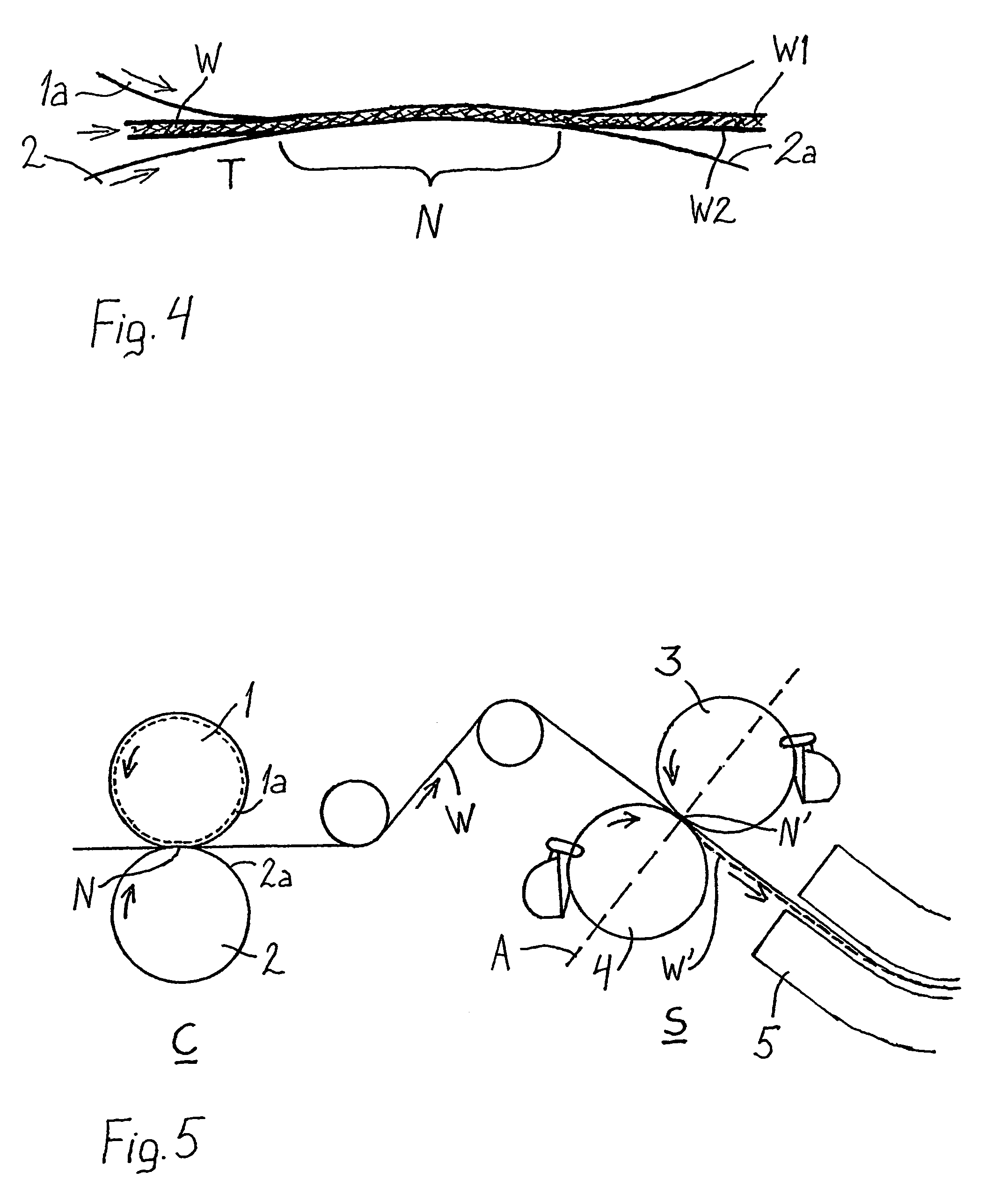
[0015]It is easier to run the web precalendered in the above-mentioned manner through a film transfer coating unit which is formed of two application rolls located on top of each other diagonally, for example in an angle of approximately 40 to 60°, or directly on top of each other (vertical angle). The rolls may also be positioned horizontally with respect to each other. In such a unit the web is run through the nip between the application rolls. If the second side whose absorption level is reduced nearly as low or at least equally low as the absorption level of the first side, is the lower side of the web passed to the nip between the rolls, the web is more reliably released last from the lower roll after the coating nip.

Problems solved by technology

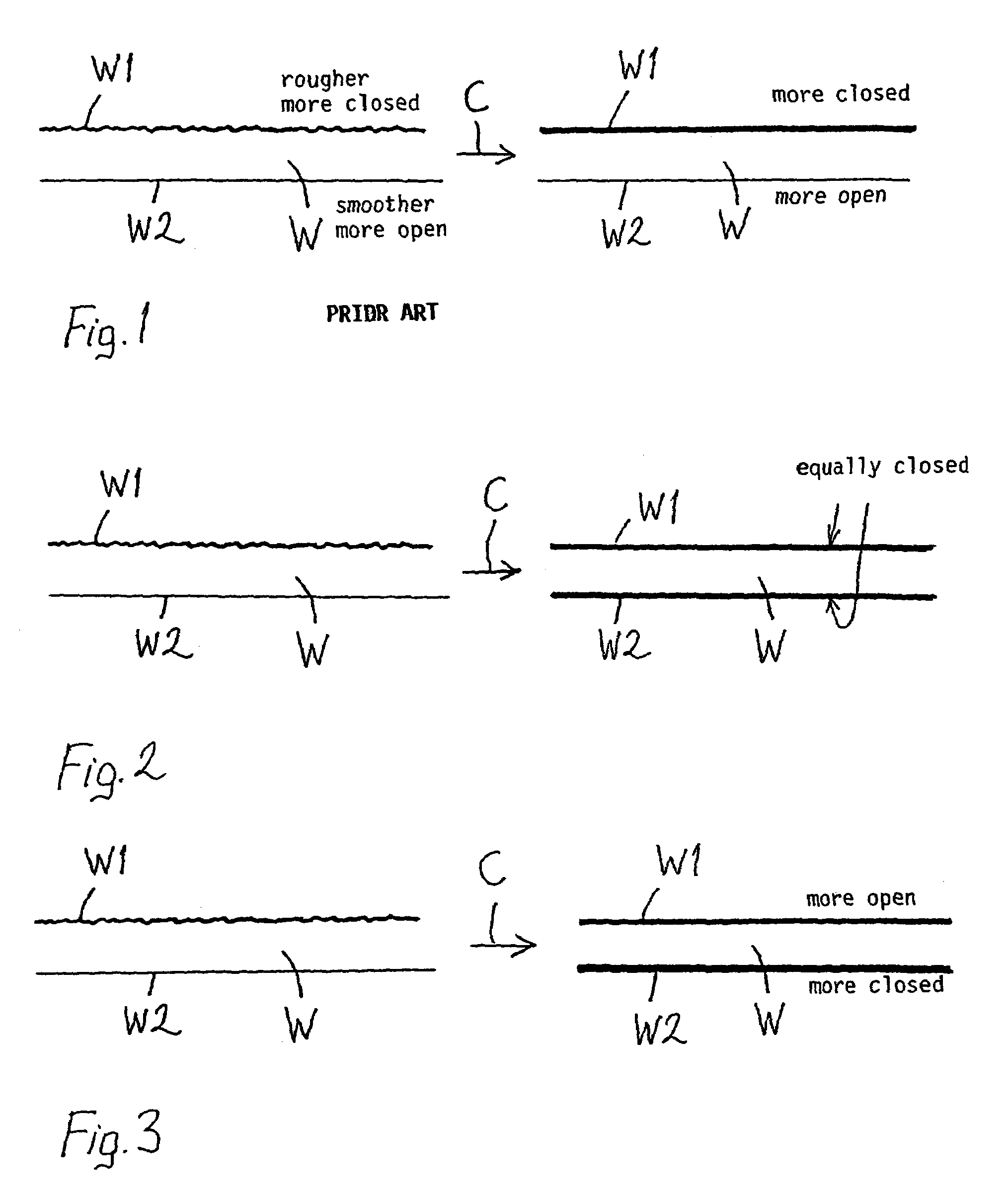
Because many machine concepts cause such an effect that the upper side, which typically is placed against the upper application roll in the coating nip as well, remains in a more closed state, and the one-sidedness in absorption resulting therefrom cannot be corrected by means of precalendering even though the smoothness would be brought on the same level, the more open lower surface absorbs too much coating colour, whereas on the upper side more coating colour remains on the surface.
Thus, due to the larger amount of coating colour, the upper side tends to follow the upper roll after the nip, and it is last released therefrom, which causes runnability problems.
In cases where mist formation takes place, the problems typically occur on that side from which the web is released last.
Then, however, another problem occurs: the quality becomes one-sided, which is not a good aspect in printing papers.

Method used


Image

  • Precalendering method, finishing method and apparatus for implementing the methods
  • Precalendering method, finishing method and apparatus for implementing the methods
  • Precalendering method, finishing method and apparatus for implementing the methods

Examples


Embodiment Construction

[0022]FIG. 1 illustrates how a paper web has been treated in solutions according to the state of the art. FIG. 1, as well as FIGS. 2 and 3 are only intended to illustrate the state of the art and the invention, and the purpose of the same is not to describe the structure of paper in detail, but some features are exaggerated for the sake of clarity. In FIG. 1, due to the earlier dewatering stages, one-sidedness occurs in the paper web W both in roughness and absorption. The absorption level is illustrated by the thickness of the lines, wherein the thicker the line, the more closed the surface and the lower the absorption level. The roughness or “coarseness”, in turn, is illustrated by the irregularity of the outline of the surface. In FIG. 1, the first surface W1 of the paper web W (the upper surface in the drawing) is rougher than the second surface W2 (the lower surface in the drawing), whereas the absorption level of the second surface W2 is higher than that of the first surface W...


PUM

PropertyMeasurementUnit
Temperatureaaaaaaaaaa
Angleaaaaaaaaaa

Abstract

A paper or paperboard web (W) is precalendered. A web that has undergone earlier dewatering stages is calendered to attain a suitable surface for the coating process. The web is calendered (C) one-sidedly in such a manner that the absorption level of the second side (W2) of the web entering the calendering, which is higher than the absorption level of the first side (W1), is reduced in the calendering nearly to the same level or at least to the same level with the first side (W1).

Description

STATEMENT AS TO RIGHTS TO INVENTIONS MADE UNDER FEDERALLY SPONSORED RESEARCH AND DEVELOPMENT[0001]Not applicable.BACKGROUND OF THE INVENTION[0002]The invention relates to a precalendering method, in which a paper or paperboard web that has undergone earlier dewatering stages is calendered to attain a suitable surface for the coating process. The invention also relates to a finishing method for paper or paperboard. Furthermore, the invention also relates to an apparatus for implementing the methods.[0003]In the papermaking process the dewatering stages include the initial dewatering that has taken place in the wire section for formation of a web, dewatering of the formed web by pressing in the press section and drying by means of heat in the drying section, in which the moisture of the web is reduced to a suitable level for further processing.[0004]After the paper has been dried, desired surface structure of the web is attained by means of a mechanical treatment applied to the surfac...

Claims


Application Information

Patent Timeline
IPC IPC(8): D21H19/76B05C1/08B05D1/28D21H19/84D21G1/00D21H23/30
CPCD21G1/00D21H23/30D21G1/006
Inventor GRON, JOHANSIPI, KARI
Owner VALMET TECH INC
Learn More