Variable frequency power system and method of use

a technology of variable frequency and power system, which is applied in the direction of magnetizing materials, cores/yokes, load balancing in dc network, etc., can solve the problem that the system cannot vary the frequency of output power, the engine driving the generator usually stalls out, and the large starting current required by the motor is normally overcom

Active Publication Date: 2007-01-30
FOUND ENTERPRISES
View PDF12 Cites 98 Cited by
  • Summary
  • Abstract
  • Description
  • Claims
  • Application Information

AI Technical Summary

Problems solved by technology

A problem with a single generator to supply power to a single motor system is that the large starting current required by the motor is normally overcome by sizing the generator as much as 40 percent larger than the main motor load to be applied to the generator.
If the motor-generator combination is less than 40 percent larger than the main electrical motor to be started, then the engine driving the generator usually stalls out when attempting to start the motor.
Another problem with fixed power supply systems is that these systems can not vary the frequency of the output power to the three phase motor, if it is required.
There is a decline in reservoir pressure due to depletion of the well.
There are mechanical problems with the wellbore, such as scaling or paraffin etc., which could cause a production decline.
There are many disadvantages to using a variable speed drive.
Use of a variable speed drive reduces the electrical efficiency of the motor and creates harmonic spikes on the generated variable frequency power supplied to the motor.
Other disadvantages are associated with the engine, generator and transformer, when using a variable speed drive.
The transformer must have a larger number of multiple voltage taps to anticipate changes in motor and cable requirements, which requires a more expensive transformer.

Method used


Image

  • Variable frequency power system and method of use
  • Variable frequency power system and method of use
  • Variable frequency power system and method of use

Examples


Embodiment Construction

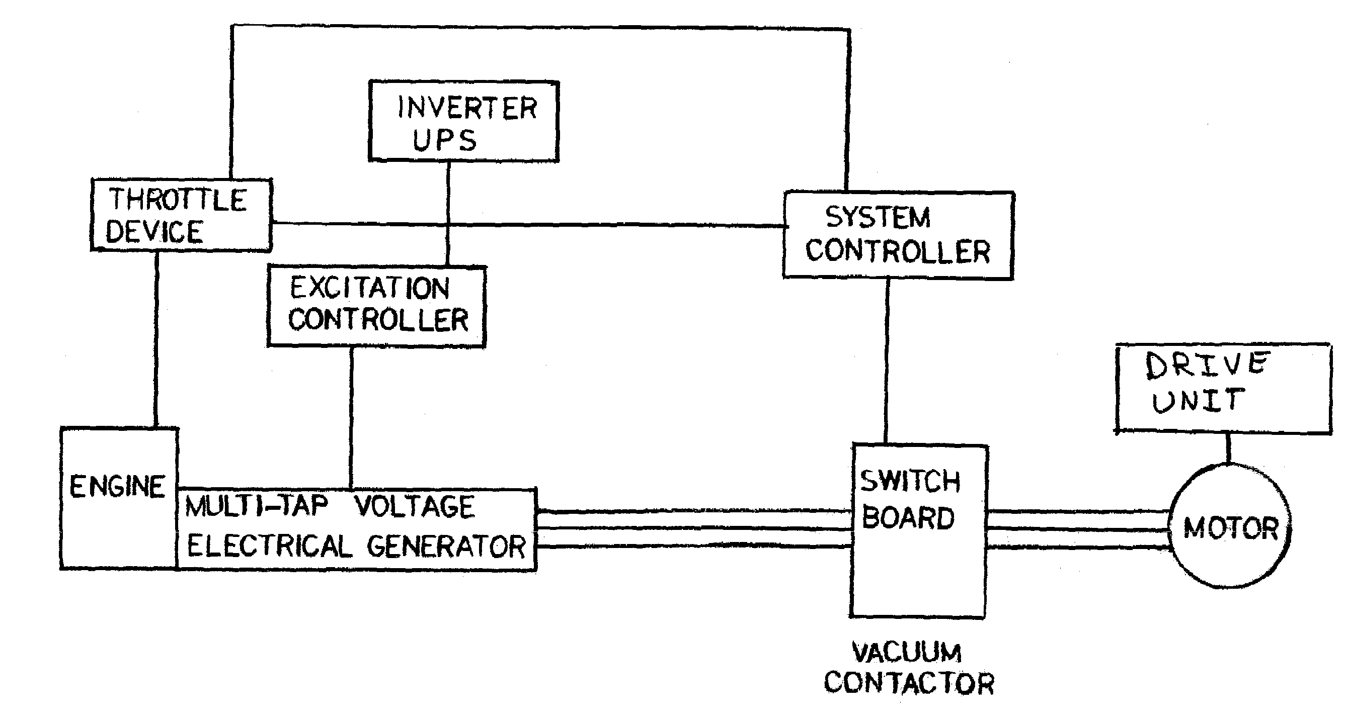
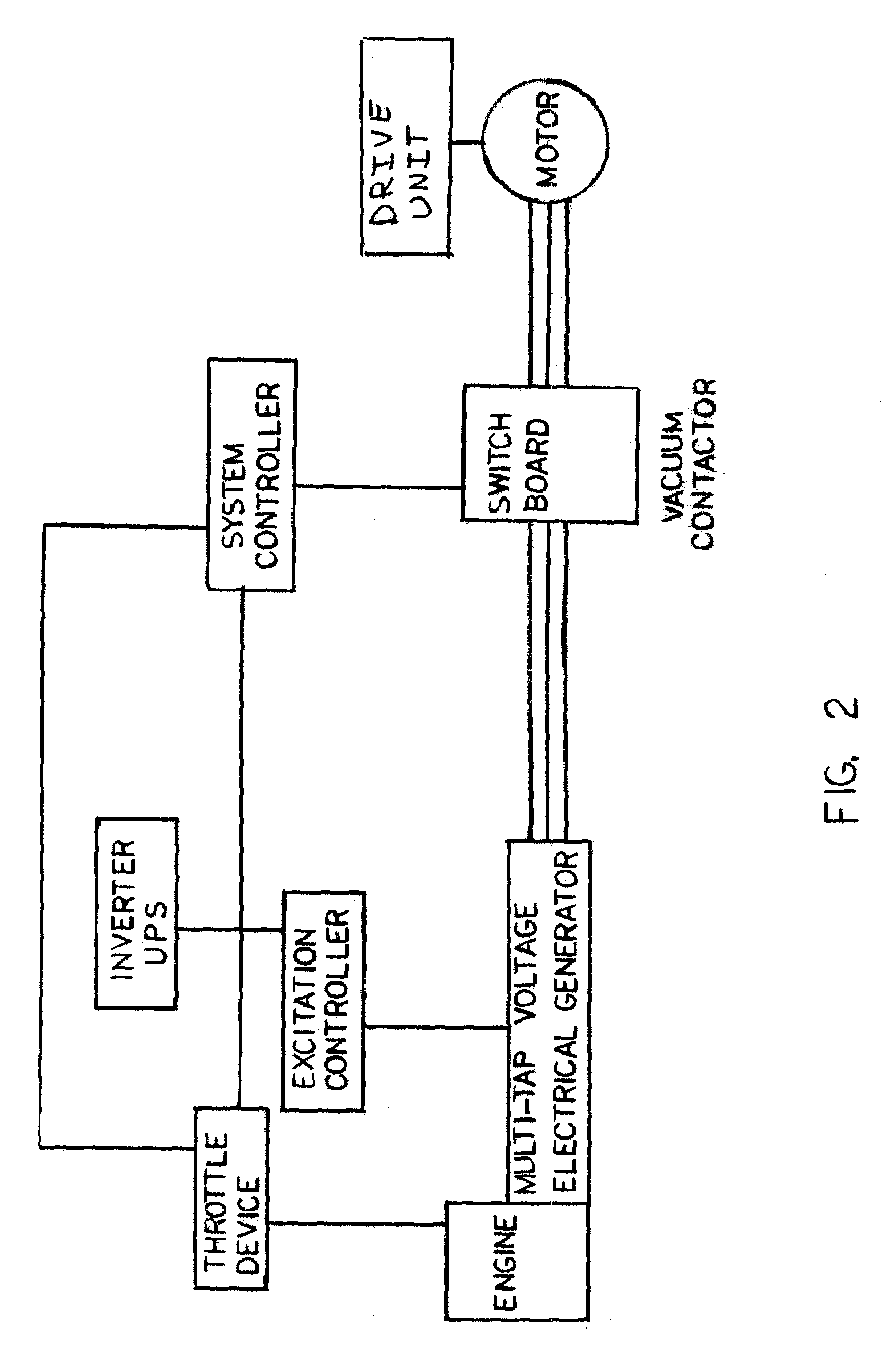
[0011]The present invention is a variable frequency power system to drive a three phase electrical motor at the frequency, voltage and amperage, as required by the motor operation to drive a driven unit. The variable frequency power system of the present invention is especially applicable where the driven unit is an electric submersible pump used in the oil and gas industry. The electric submersible pump is driven by alternating current (AC) three phase electrical motor which exhibits a non-linear relationship between rotational speed and torque load due to the inherent characteristics of centrifugal pumping systems. The variable frequency power system includes a generator driven by a power source. The variable frequency power system includes a specially programmed logic circuit in a system controller, which interfaces with the power source of the generator. The programmed logic circuit is designed to monitor and control the driven unit by monitoring the conditions of the driven uni...


PUM


Abstract

A variable frequency power system with a power source having a rotating output and a speed control to regulate rotational speed of the rotating output. A generator coupled to and driven by the rotating output of the power source, whereby the speed control of the power source directly controls output power frequency of the generator due to control of rotational frequency of the rotating output. A voltage regulator connected between the generator and the motor regulates output voltage from the generator to the electrical motor load. A system controller controls output power frequency of the generator. The system controller interfaces with the speed control of the power source and configured to monitor generator output and operational conditions of the electrical motor load. The system controller adjusts the speed control based on generator output and operational conditions of the electrical motor load.

Description

BACKGROUND OF INVENTION[0001]The present invention generally relates to providing variable electrical power to a three phase electrical motor. More specifically, the present invention relates to varying electrical power to a three phase electrical motor based on varying frequency input turning an electrical generator which provides electrical power to the motor, in order to overcome variable conditions encountered by the motor that require a variation in electrical power to the motor.[0002]It is known to use three phase generators to supply the power to drive three phase motors. Normally, fixed power supply systems using three phase generators are operated at a constant speed to deliver three phase electrical energy of constant frequency to supply three phase power to three phase motors. There are currently two types of three phase fixed power supply systems in common use today. They are the 50 hertz and the 60 hertz power supply systems, which are used to drive electrical motors ra...

Claims


Application Information

Patent Timeline
Patent Type & Authority Patents(United States)
IPC IPC(8): H02P9/00F02D29/06H02H7/06H02P25/30H02P7/00H02J7/00H02P1/30H02P9/42
CPCH02P9/42
Inventor PETTIGREW, DANA ROBERT
Owner FOUND ENTERPRISES
Why Eureka
Try Eureka