Integrated mobile communication antenna

a mobile communication antenna and integrated technology, applied in the field of mobile communication antennas, can solve the problems of not having a structural design for integrating the functional modules of digital cameras or other functional modules, not offering an integrated design with the antenna, etc., and achieve the effect of reducing the total size of the mobile communication devi

Active Publication Date: 2007-01-30
IND TECH RES INST
View PDF8 Cites 50 Cited by
  • Summary
  • Abstract
  • Description
  • Claims
  • Application Information

AI Technical Summary

Benefits of technology

[0006]In view of the aforesaid concerns, the primary object of the invention is to provide an integrated mobile communication antenna that has a short-circuiting metal cylinder to integrate the antenna and other functional modules of a mobile communication device so that the total size of the mobile communication device may be reduced.
[0007]Another object of the invention is to reduce electromagnetic interference between the antenna and other integrated functional modules and improve the service quality of the mobile communication device by grounding the metal cylinder.

Problems solved by technology

As lean profile and light weight have become basic conditions of development for mobile communication devices, how to integrate the antenna and other functional modules in the limited space inside the mobile communication device and still meet the multiband operation requirements is an important issue that all mobile communication device makers now encounter.
However, the known conventional techniques for the antenna and mobile communication devices, such as U.S. Pat. Nos. 6,614,400 and 6,717,548 concerning the antenna for mobile phone multiband operation, do not have a structural design for integrating the functional modules of the digital camera or other functional modules.
They also do not offer an integrated design with the antenna.
All this indicates that even in the highly competitive mobile phone market, a technique for integrating the antenna and functional modules is still not available.
As the antenna and other functional modules are usually designed independently and located separately, they result in a great waste of the limited space in the mobile communication device.
Moreover, if they are located close to each other, electromagnetic interference occurs between the antenna and other functional modules, and the quality of the entire mobile communication device is affected.

Method used


Image

  • Integrated mobile communication antenna
  • Integrated mobile communication antenna
  • Integrated mobile communication antenna

Examples


first embodiment

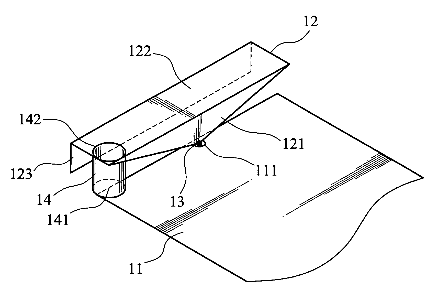
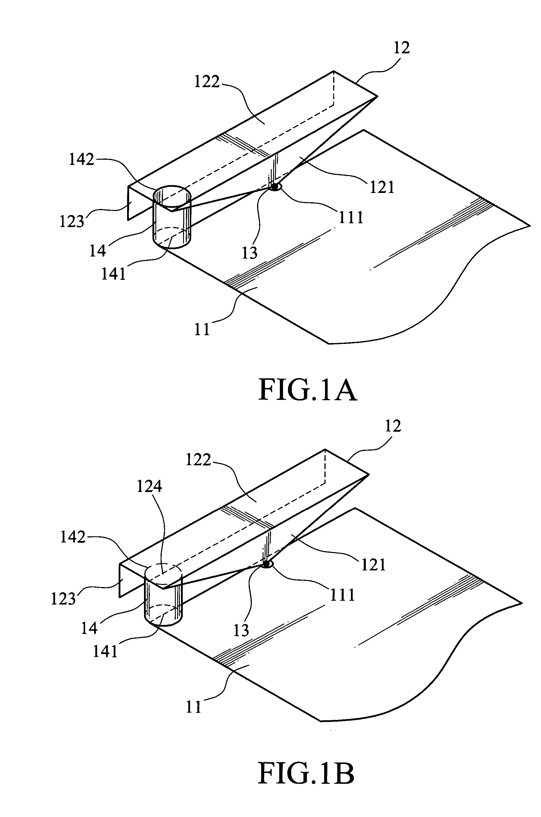
[0026]Refer to FIGS. 1A and 1B for a first embodiment and a second embodiment of the invention.

[0027]The structures of the antenna are substantially the same. The main elements are depicted as follows:

[0028](a) A ground 11 has a via-hole 111 to allow an external signal source (not shown in the drawings) to pass through. It is formed substantially rectangular but may be adjusted according to the interior space of the mobile communication device where it is housed. Forming of the ground shape is a technique known in the art, so details are omitted here.

[0029](b) A radiating member 12 is located above the ground 11 and has a feeding portion 13 to receive signals from the external signal source via electrical connection and through the via-hole 111. The feeding portion 13 may also be electrically connected to a feeding member (not shown in the drawings) to receive signals from the external signal source through the via-hole 111.

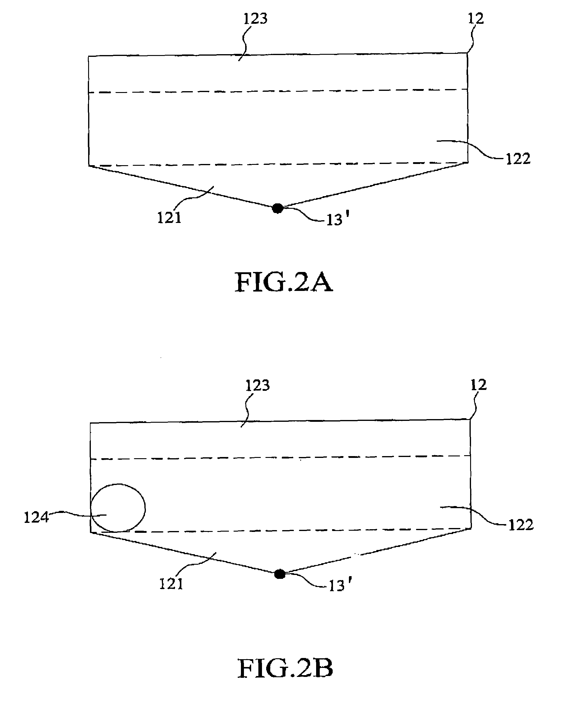
[0030]The radiation member 12 (refer to FIG. 2A for the fla...

second embodiment

[0041]For housing an exposed functional module (such as the digital camera functional module), in addition to the lower opening 141 on the short-circuiting member 14, the second end of the short-circuiting member 14 connected to the radiating member 12 also has an upper opening 142 to expose the functional module. This is the second embodiment shown in FIGS. 1B and 2B. The radiating member 12 has an opening 124 corresponding to the upper opening 142 with substantially the same size and shape so that the functional module may be fully exposed.

[0042]The short-circuiting member 14 may be formed as desired without restriction. It is generally circular, elliptical (as shown in FIG. 9A), rectangular (as shown in FIG. 9B), or polygonal (as shown in FIG. 9C).

[0043]Refer to FIG. 3 for the measured return loss of the antenna according to the invention. The ground 11 has a length of about 118 mm and a width of about 60 mm. The radiating member 12 has a first sub-radiating member 121 with a bot...


PUM


Abstract

An integrated antenna for mobile communications. A short-circuiting metal cylinder is provided in the antenna for arranging other functional modules such that the antenna and related circuits may have better integration. The provided antenna includes a ground with a via-hole; a radiating member arranged on the ground and having a feeding portion for receiving signals via electrical connection through the via-hole; and a short-circuiting member having a space, a first end of which is electrically connected to the ground substantially vertically, and the other end of which is electrically connected to the radiating member. The radiating member further includes a first sub-radiating member, a second sub-radiating member and a third sub-radiating member. The first sub-radiating member is substantially triangular, and the second sub-radiating portion is substantially parallel to the ground. The third sub-radiating member is substantially parallel to the first sub-radiating member.

Description

FIELD OF THE INVENTION[0001]The invention relates to a mobile communication antenna, and particularly to a mobile communication antenna that integrates other functional modules and meets multiband operation requirements of mobile communication devices.BACKGROUND OF THE INVENTION[0002]With increasing popularity of mobile communication devices and fierce competition in the market place, manufacturers are constantly adding more functions to mobile communication devices to enhance product competitiveness. For instance, adding built-in digital cameras to mobile phones has become very fashionable in recent years.[0003]As lean profile and light weight have become basic conditions of development for mobile communication devices, how to integrate the antenna and other functional modules in the limited space inside the mobile communication device and still meet the multiband operation requirements is an important issue that all mobile communication device makers now encounter. Take the highly...

Claims


Application Information

Patent Timeline
Patent Type & Authority Patents(United States)
IPC IPC(8): H01Q1/22
CPCH01Q1/243H01Q9/0421H01Q1/52
Inventor TANG, CHIA-LUNYEH, SHIH-HUANGWONG, KIN-LUCHIEN, SHAO-LUN
Owner IND TECH RES INST
Why Eureka
Try Eureka