Interleaver, deinterleaver, interleaving method, and deinterleaving method for OFDM data

a technology of interleaving and data, applied in the field of coded orthogonal frequency division multiplexing, can solve the problems that the design that uses a memory buffer may get clogged with data rates, and achieve the effect of saving both latency and power

Active Publication Date: 2007-01-30
CISCO TECH INC
View PDF3 Cites 172 Cited by
  • Summary
  • Abstract
  • Description
  • Claims
  • Application Information

AI Technical Summary

Benefits of technology

[0014]Furthermore, one embodiment of the present invention provides an interleaver that achieves both symbo

Problems solved by technology

However, a design that uses a memory buffe

Method used


Image

  • Interleaver, deinterleaver, interleaving method, and deinterleaving method for OFDM data
  • Interleaver, deinterleaver, interleaving method, and deinterleaving method for OFDM data
  • Interleaver, deinterleaver, interleaving method, and deinterleaving method for OFDM data

Examples


embodiment 200

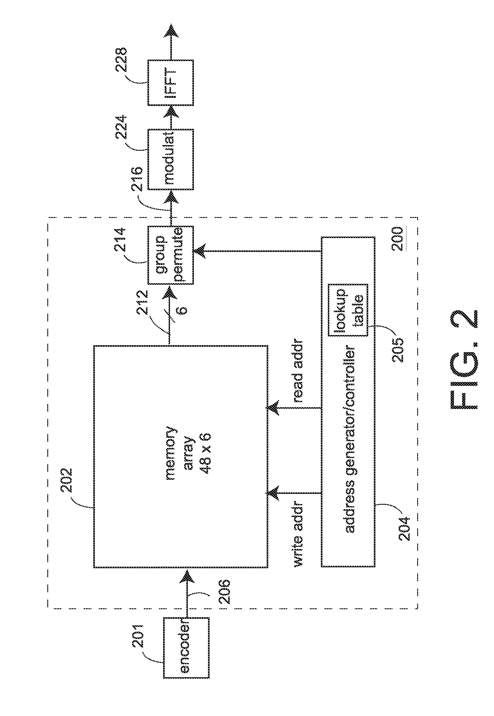
[0035]FIG. 2 shows one interleaver embodiment 200 that includes a memory 202. An input 206 is in the form of blocks of coded bit data, e.g., from an encoder 201 of a transmit signal processor. The output 216 of the interleaver 200 is in the form of subcarriers (also called groups) of data. In a typical COFDM transmitter, the subcarrier data is modulated, e.g., in a modulator shown as 224, and the modulated data is inverse discrete Fourier transformed in an inverse Fast Fourier transform (IFFT) unit shown as 228.

[0036]The bits of a block from the encoder are written into the memory 202, and then the bits of that block are read out as data 212 in a different order. The organization of the bits in the memory 202 may be described by an array of rows and columns, called the “interleaver array” herein, that can describe the order in which the bits of a block are written into and the order in which the bits are read out from the array. Such orders of reading and writing are controlled by a...

embodiment 300

[0057]The embodiment 300 also includes a group bit-permute unit that is required for some modulation schemes and data rates, and an address generator / controller 320.

embodiment 400

[0058]FIG. 4 shown another embodiment 400 of a parallel interleaver that accepts data from an encoder more than one bit at a time, e.g., one di-bit at a time. In this embodiment, the input data is directly written into the memory 402 at the input rate, e.g., one di-bit at a time. Writing one di-bit at a time reduces the memory bandwidth requirement of a two stage buffered interleaver by a factor of two, e.g., to a maximum of 36 Mbps for 64QAM. Other implementations may include an encoder that provides more than two bits at a time and an interleaver that includes a memory that is read into than two bits at a time.

[0059]The two bits at a time are written into memory 402 that will contain two interleaver arrays, i.e., two symbols, while one bit from each of the written two-bits in the second memory array 404 is selected by a multiplexer switch—a selector—412. The selected one-symbol of the multiplexer output is sent to the output bus 414 through a group permute unit 410 that may be nee...


PUM


Abstract

An interleaver and interleaving method each includes two stages, and is useful in coded orthogonal frequency division multiplexed (COFDM) wireless local area networks. A first stage performs a first block permutation and a second stage performs bit order permutation to effectuate a second group permutation. A corresponding de-interleaver does just the opposite at the receiver. A double-buffer version includes writing data into one memory block in a first order while reading data from the second block in a second order, with the first and second orders selected to effectuate the first block permutation.

Description

RELATED PATENT APPLICATIONS[0001]This invention claims benefit of U.S. Provisional Patent Application Ser. No. 60 / 322,383 filed Sep. 14, 2001. This invention also claims benefit of two U.S. Provisional Patent Applications. The first is Ser. No. 60 / 277,370, filed Mar. 19, 2001, and titled SYSTEM USING SINGLE CHIP WIRELESS LAN MODEM AND SINGLE CHIP RADIO TRANSCEIVER AND APPARATI, METHODS, AND SOFTWARE PRODUCTS USED THEREIN OR THEREWITH. The second is Ser. No. 60 / 283,609, filed Apr. 13, 2001, and titled WIRELESS COMMUNICATION SYSTEM. Such provisional patent applications are incorporated herein by reference.BACKGROUND OF THE INVENTION[0002]1. Field of the Invention[0003]The present invention relates to coded orthogonal frequency division multiplexing (COFDM), and more particularly to interleaving for wireless local area networks (WLANs) using COFDM.[0004]2. Description of Related Art[0005]Coded orthogonal frequency division multiplexing (COFDM) is a type of radio modulation that splits ...

Claims


Application Information

Patent Timeline
IPC IPC(8): H04J11/00
CPCH03M13/2707H04L1/0071H04L1/0054H04L1/0043
Inventor ARIVOLI, THANGADURAIO'SULLIVAN, JOHN D.
Owner CISCO TECH INC
Why Eureka
Try Eureka