Check patentability & draft patents in minutes with Patsnap Eureka AI!

Clock recovery method by phase selection

a phase selection and clock recovery technology, applied in the field of methods, can solve the problems of excessive power dissipation, complex design of circuits, and undesirable power dissipation

Inactive Publication Date: 2007-01-30
KARMIC DESIGN USA
View PDF8 Cites 2 Cited by
  • Summary
  • Abstract
  • Description
  • Claims
  • Application Information

AI Technical Summary

Benefits of technology

[0009]A further object of the present invention is to provide a method that produces a PLL clock with a phase nearest to that of an external clock while consuming minimal power.

Problems solved by technology

The design of these systems is complex and the circuits consume substantial power.
Here, especially, the excessive power dissipation is undesirable.
One problem with this circuit is the complexity of the phase comparator and variable delay circuit.
Another problem is that the circuit corrects the phase relationship even when the phase difference is small.
This results in output jitter and substantial power dissipation during the correction cycle.
Finally, this method is poor for applications requiring a wide frequency range and where the frequency of CLKOUT is N times that of CLKIN.

Method used


Image

  • Clock recovery method by phase selection
  • Clock recovery method by phase selection
  • Clock recovery method by phase selection

Examples


Embodiment Construction

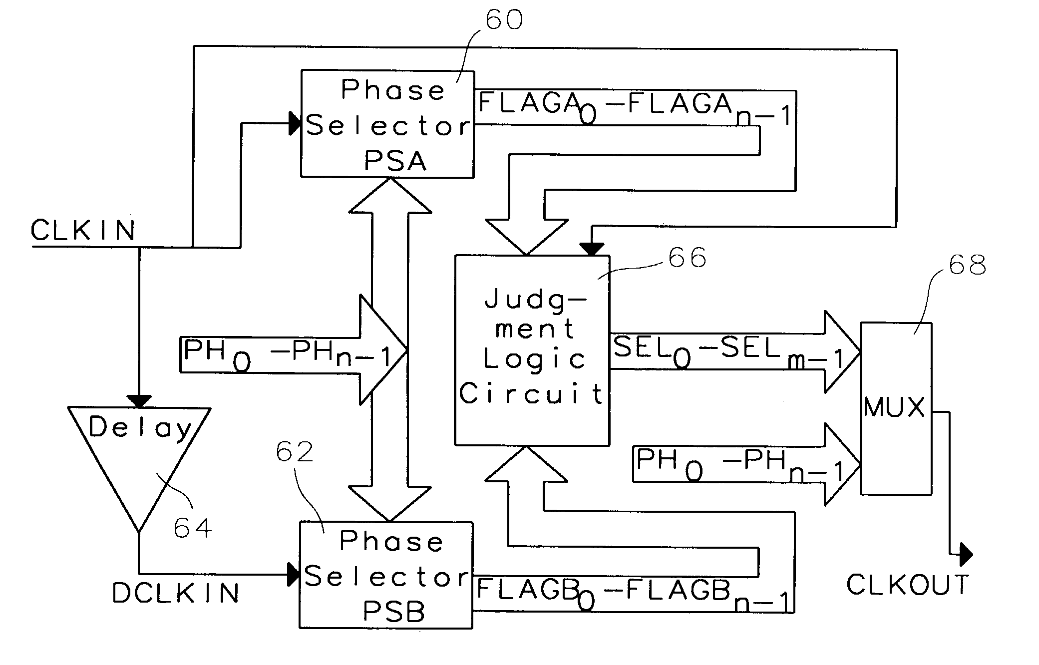
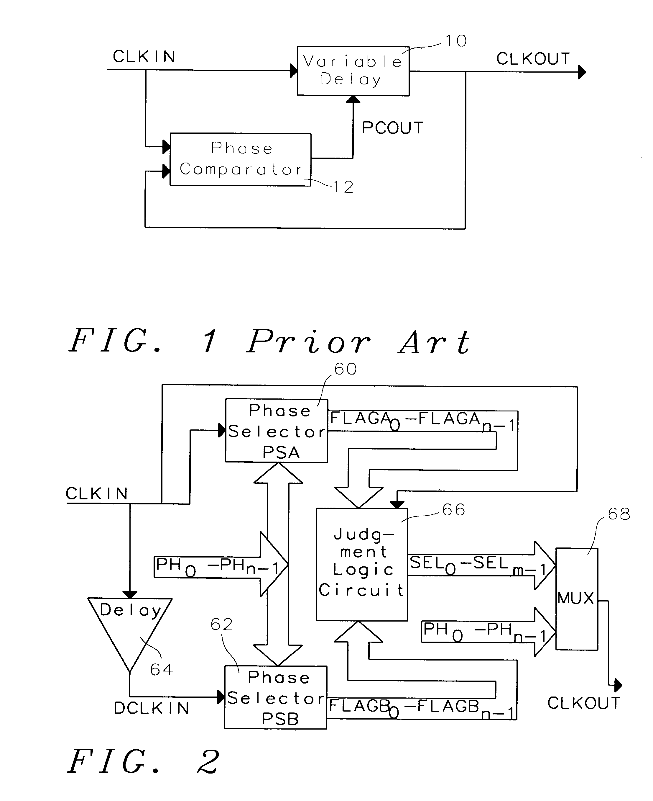
[0019]Refer now to FIG. 2, depicting in block diagram the phase selection method of the present invention. Two identical phase selectors, PSA 60 and PSB 62 are provided. A detailed description of the operation of the phase selector (60 and 62) will be discussed later. An external clock, CLKIN is applied to PSA 60 and also to a delay circuit 64. The output of the delay circuit 64 is the applied to PSB 62. Both PSA 60 and PSB 62 have a plurality (n) of phase clocks (PH0 through PHn−1) applied. These phase clocks are approximately n times the frequency of CLKIN and are shifted equally by approximately 360° / n (PH1 lags PH0 by 360° / n, PH2 lags PH1 by 360° / n, etc.). PSA has an output bus FLAGA with n bits labeled FLAGA0 through FLAGAn−1; similarly, PSB 62 has an output bus FLAGB with n bits labeled FLAGB0 through FLAGBn−1. CLKIN, FLAGA and FLAGB are applied to a judgement logic circuit 66. The output of the judgement logic circuit 66 is an m-bit select signal that is applied along with PH...


PUM


Abstract

The present invention demonstrates a method and circuit where a plurality of phase clocks from a “frequency lock only” PLL are used to sample an input clock CLKIN. This results in a series of signals from which the phase clock most in synchronization with CLKIN can be determined and presented to the output CLKOUT. If used for data sampling, a phase clock that lags the phase clock most in synchronization may be selected to appear at CLKOUT. This guarantees that sampled data are static during sampling. This system is less complex and consumes minimal power over systems using variable delay circuits.

Description

BACKGROUND OF THE INVENTION[0001]1. Field of the Invention[0002]The invention generally relates to a method used in semiconductor manufacturing and, more particularly, to a phase-locked loop (PLL) method used to synchronize circuit timing in the fabrication of integrated circuits (ICs).[0003]2. Description of Prior Art[0004]Because sequential data may vary in both frequency and phase, phase-locked loops with both frequency and phase locking are typically used to sample that data. The design of these systems is complex and the circuits consume substantial power. One application where this is utilized is in the transfer of data to a display in a portable computer. Here, especially, the excessive power dissipation is undesirable.[0005]Refer now to FIG. 1 showing a typical PLL system for generating an internal synchronization clock (CLKOUT). The reference clock (CLKIN) is applied to the input of a variable delay circuit 10 and the input of a phase comparator 12. The output, CLKOUT, of t...

Claims


Application Information

Patent Timeline
IPC IPC(8): H03D3/24H03L7/00H03D13/00H03L7/06
CPCH03L7/06H03D13/003
Inventor CAO, JIAO MENG
Owner KARMIC DESIGN USA
Features
  • R&D
  • Intellectual Property
  • Life Sciences
  • Materials
  • Tech Scout
  • Unparalleled Data Quality
  • Higher Quality Content
  • 60% Fewer Hallucinations
Learn More