Pretensioner

Inactive Publication Date: 2007-02-06
JOYSON SAFETY SYST JAPAN KK
View PDF32 Cites 25 Cited by
  • Summary
  • Abstract
  • Description
  • Claims
  • Application Information

AI Technical Summary

Benefits of technology

[0009]The present invention has been made in view of such problems, and an object of the invention is to provide a small, light, and inexpensive pret

Problems solved by technology

As a result, the number of components and the number of assembly processes increase, and the cost is increased.
However,

Method used


Image

  • Pretensioner
  • Pretensioner
  • Pretensioner

Examples


Example

[0034]An embodiment of the present invention will be described below with reference to the drawings.

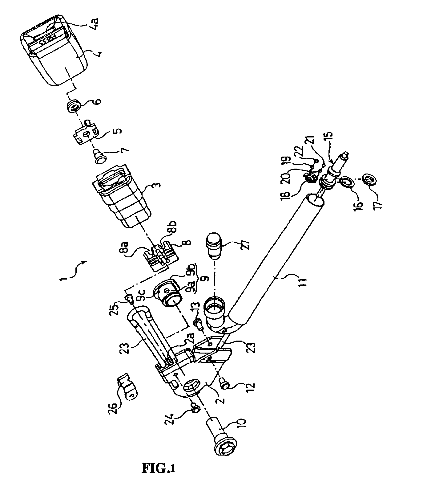
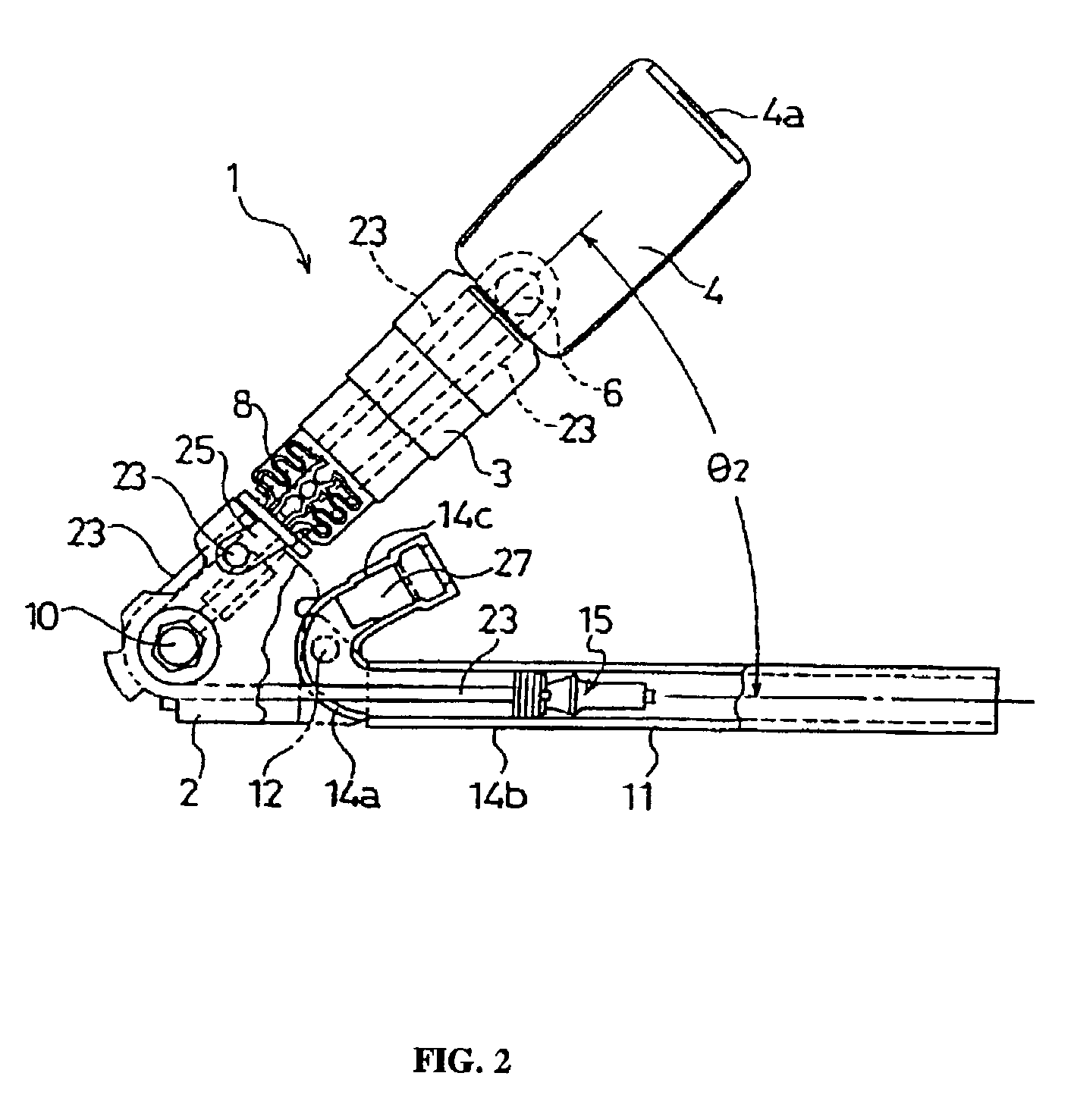
[0035]FIG. 1 is an exploded perspective view showing an embodiment in which a pretensioner according to the present invention is applied to as a buckle pretensioner, and FIG. 2 is a view showing an assembled state of the buckle pretensioner of this embodiment.

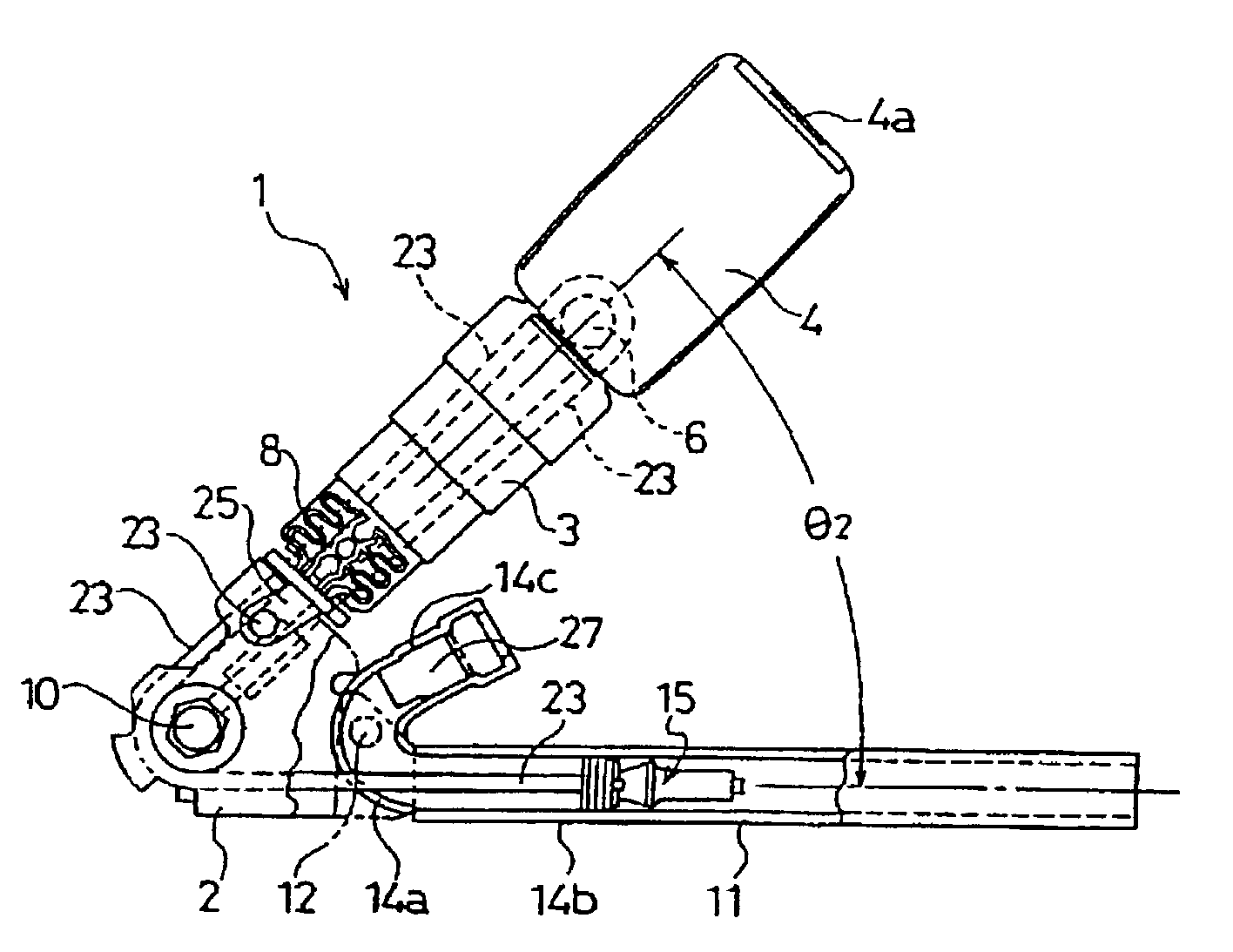
[0036]As shown in FIGS. 1 and 2, in a buckle pretensioner 1 of this embodiment, one end of a prismatic inner cover 3 that can be axially telescopic is attached to a bracket 2, and the other end of the inner cover 3 is attached to a buckle assembly 4. A wire plate 5 is mounted in the buckle assembly 4 on the side opposite from an insertion slot 4a of a tongue (not shown), and a pulley 6 is rotatably supported on the wire plate 5 by a rivet 7. A wire holder 8 is attached to the bracket 2 inside one end of the inner cover 3, and has a pair of grooves 8a and 8b for holding and guiding a wire which is described further below.

[0037]A c...


PUM


Abstract

A pretensioner including a cylinder in which a piston slides. A side of the pipe attached to a bracket is curved at a predetermined angle. One linear portion of the pipe serves as the cylinder, and the other linear portion of the pipe serves as a gas-generator accommodating portion that accommodates a gas generator. A wire passing hole through which a wire passes is bored coaxially with the center axis of the piston sliding portion of the pipe. The piston sliding portion and the gas-generator accommodating portion can be formed of the single pipe, and the gas generator and the wire can be prevented from interfering with each other.

Description

BACKGROUND OF THE INVENTION[0001]The present invention belongs to a pretensioner which is used, for example, in a seat belt device attached to the seat of a vehicle, such as a car. The pretensioner typically applies a tension on a seat belt and increases the restraint force on the occupant in the case of an emergency such as, for example, a vehicle collision. More particularly, the present invention relates to a pretensioner in which a piston is operated by the pressure of gas generated by a gas generator so as to apply a tension to a seat belt.[0002]Conventionally, the seats of vehicles, such as cars, are provided with seat belt devices, and the seat belt devices serve to protect the occupant by restraining the occupant with the seat belt and reducing the inertial movement of the occupant when an extremely high vehicle deceleration is caused in the case of an emergency such as a vehicle collision. Some of such conventional seat belt devices have a pretensioner that quickly restrain...

Claims


Application Information

Patent Timeline
IPC IPC(8): B60R22/46B60R22/40B60R22/195
CPCB60R22/1952B60R22/1955
Inventor NAKANO, YOSHIYUKIIWAI, MASAHIKONAKAYAMA, TADAHIRO
Owner JOYSON SAFETY SYST JAPAN KK
Why Eureka
Try Eureka