Stabilized filament drawing device for a meltspinning apparatus and meltspinning apparatus including such stabilized filament drawing devices

a technology of stabilizing and drawing devices, which is applied in the direction of filament/thread forming, manufacturing tools, and melt spinning methods, etc., can solve the problems of reducing the long range uniformity affecting the quality of the collected nonwoven web, and unpredictable variations in the looping of the filament, so as to prevent the propagation of the vortex, significantly reduce the turbulence, and reduce the randomness of the filament trajectories

Inactive Publication Date: 2007-02-06
AKTIENGES ADOLPH SAURER
View PDF28 Cites 20 Cited by
  • Summary
  • Abstract
  • Description
  • Claims
  • Application Information

AI Technical Summary

Benefits of technology

[0015]In accordance with the principles of the invention, the guides of the drawing device separate the descending sheet or curtain of airborne filaments into two distinct sheets or curtains that are spaced apart in the machine direction. The individual guides of the stabilizing device promote a barrier action that counteracts the vortices and, thereby, prevents the propagation of the vortices from the drawing device outlet to the collection device. This reduces the randomness of the filament trajectories by eliminating or, at the least, significantly reducing turbulence. The rotation of the inclined surfaces of the guides relative to the machine direction is believed to enhance entanglement of the deposited filaments constituting the nonwoven web.
[0016]The individual guides channel the high-velocity process air into discrete, aerodynamic columns that remain substantially undisturbed and intact between the drawing device outlet and the collection device. The guides also dissipate filament energy, which slows the filament velocity. Because of these beneficial effects, filament looping is more controlled and compact, which increases filament entanglement and thereby enhances web integrity by providing a greater degree of filament interlocking. Because the two rows of guides are not separated by open areas, ambient air cannot be aspirated between the individual guides, which prevents or, at the least, lessens filament twisting and bundling. The elimination of open areas also permits the drawing device outlet to be placed closer to the collection device during operation without inducing web striping. The guides also eliminate, or at least reduce, the inward movement of airborne filaments proximate the side edges of the drawing device outlet.
[0018]In accordance with the principles of the invention, the filaments may be drawn to a smaller diameter using significantly less air flow in the drawing device. The savings in process air consumption translates to significant customer savings, reductions in capital equipment costs as the air handling capacity of blowers serving the filament drawing device may be reduced, and reduced consumable costs.

Problems solved by technology

Certain characteristics of the high-velocity stream of process air used to attenuate the filaments are believed to degrade the quality of the collected nonwoven web.
The interaction of the lateral vortices with the descending filaments and the high-velocity of the stream of process air causes unpredictable variations in the looping of the filaments.
As a result, localized areas of relatively low web density and relatively high web density result that reduces the long range uniformity of the collected nonwoven web.
This loss of uniformity may be undesirable for those end products intended to be fluid impervious because the low-density areas may provide leakage paths through the material.
The randomized movement of the airborne filaments decreases the integrity of the nonwoven web due to variations in coverage.
The rows of guide fins fail to prevent the difficulties associated with the mixing of aspirated secondary air and the high-velocity process air exiting the drawing device and introduce additional artifacts into the structure of the nonwoven web.
The striping reduces the integrity of the nonwoven web and causes undesirable formation variations.
However, as the distance is increased between the drawing device outlet and the collection device, chaotic movement of the filaments increases the loop size of the collected filaments and bundling or twisting.
Conventional guide fins cannot eliminate the lateral vortices from the high-velocity air exiting the drawing device.
The inability to eliminate the lateral vortices further increases the randomness of, and lack of control over, the trajectories of the descending filaments.
These conventional guide fins are formed from bent sheet metal, which lacks robustness.
As a result, the guide fins may be easily bent out of position by accidental contact.
However, increasing the line speeds may also increase the problems associated with controlling the properties of the resulting nonwoven web mentioned above.
The consequence is that, although the preferential orientation increases the web strength in the machine direction, web strength is effectively lost in the cross-machine direction.

Method used


Image

  • Stabilized filament drawing device for a meltspinning apparatus and meltspinning apparatus including such stabilized filament drawing devices
  • Stabilized filament drawing device for a meltspinning apparatus and meltspinning apparatus including such stabilized filament drawing devices
  • Stabilized filament drawing device for a meltspinning apparatus and meltspinning apparatus including such stabilized filament drawing devices

Examples


Embodiment Construction

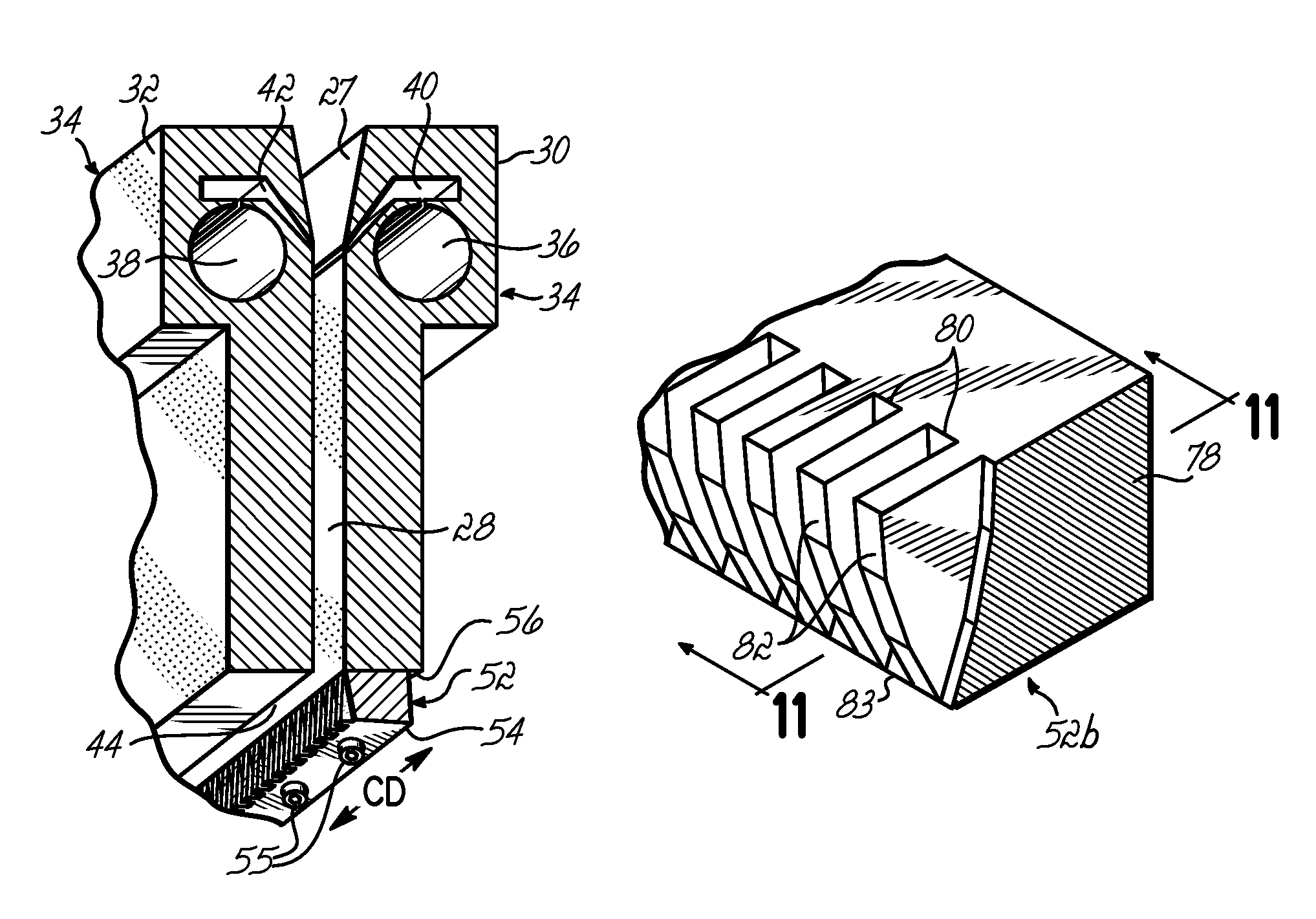
[0039]The invention is directed to apparatus and method for controlling the flight of spunbond filaments in the space between the slotted outlet of a drawing device and a collection device. To that end, a drawing device includes multiple guides that interact with the high-velocity air flow and entrained filaments to influence filament laydown on the collection device. Although the invention will be described herein as being associated with an exemplary meltspinning system, it should be understood that modifications to the exemplary meltspinning system described herein could be made without departing from the intended spirit and scope of the invention.

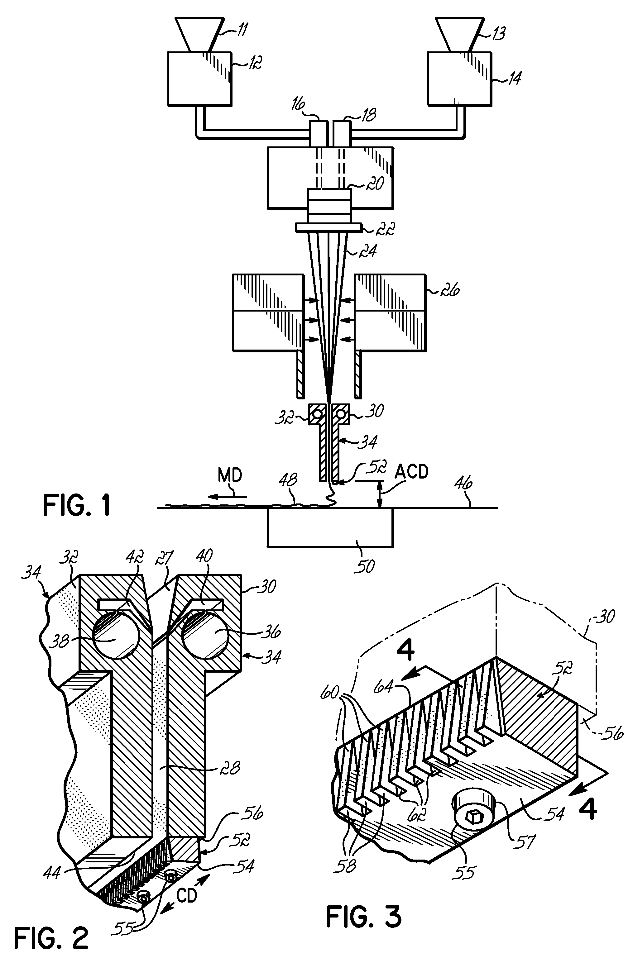
[0040]With reference to FIG. 1, a spunbonding apparatus 10 is equipped with a pair of screw extruders 12, 14 that each convert a solid melt-processable thermoplastic polymer into a molten state and transfer the molten thermoplastic polymers under pressure to a corresponding set of metering pumps 16, 18. Pellets of thermoplastic polymers...


PUM

PropertyMeasurementUnit
rotational anglesaaaaaaaaaa
diametersaaaaaaaaaa
temperatureaaaaaaaaaa

Abstract

A stabilized filament drawing device for a meltspinning apparatus and a meltspinning apparatus including the stabilized filament drawing device. The stabilized filament drawing device applies a high-velocity flow of air to attenuate the filaments, which are discharged from a device outlet in a discharge direction. The filament drawing device includes multiple inclined guides adjacent to the outlet that cause the filaments and high-velocity flow of air to deviate from the discharge direction. Each of the guides has a major surface that is angled relative to a common plane containing the discharge direction and a cross-machine direction of the device outlet of the filament drawing device. The guides are oriented such that the major surface is also inclined relative to the discharge direction.

Description

CROSS-REFERENCE TO RELATED APPLICATIONS[0001]This application is a continuation-in-part of application Ser. No. 10 / 714,778, filed Nov. 17, 2003, the disclosure of which is hereby fully incorporated by reference herein.FIELD OF THE INVENTION[0002]The invention relates generally to apparatus for forming spunbond nonwoven webs and, more particularly, to apparatus and methods for stabilizing the paths of airborne filaments in meltspinning devices.BACKGROUND OF THE INVENTION[0003]Nonwoven webs and their manufacture from melt-processable thermoplastic polymers has been the subject of extensive development resulting in a wide variety of materials for numerous commercial applications. Nonwoven webs formed from a spunbond process consist of a sheet of overlapped and entangled filaments or fibers of melt-processable thermoplastic polymers. A spunbond process generally involves extruding a dense curtain of semi-solid filaments from a spinneret of a spin pack. The descending curtain of filament...

Claims


Application Information

Patent Timeline
Patent Type & Authority Patents(United States)
IPC IPC(8): B28B5/00D01D5/098D04H3/16
CPCD01D5/0985D04H3/16D04H3/03
Inventor BENTLEY, RACHELLECRANE, PATRICK L.THOMPSON, MATTHEW DUANE
Owner AKTIENGES ADOLPH SAURER
Why Eureka
Try Eureka