Imaging apparatus and method

Inactive Publication Date: 2007-02-06
TERAVIEW
View PDF13 Cites 60 Cited by
  • Summary
  • Abstract
  • Description
  • Claims
  • Application Information

AI Technical Summary

Benefits of technology

[0013]The use of just a single frequency through the sample at any one time me

Problems solved by technology

Pulsed sources suffer from the drawback that they are expensive and also it is difficult to efficiently transmit pulses down optical waveguides etc.
The c

Method used


Image

  • Imaging apparatus and method
  • Imaging apparatus and method
  • Imaging apparatus and method

Examples


Example

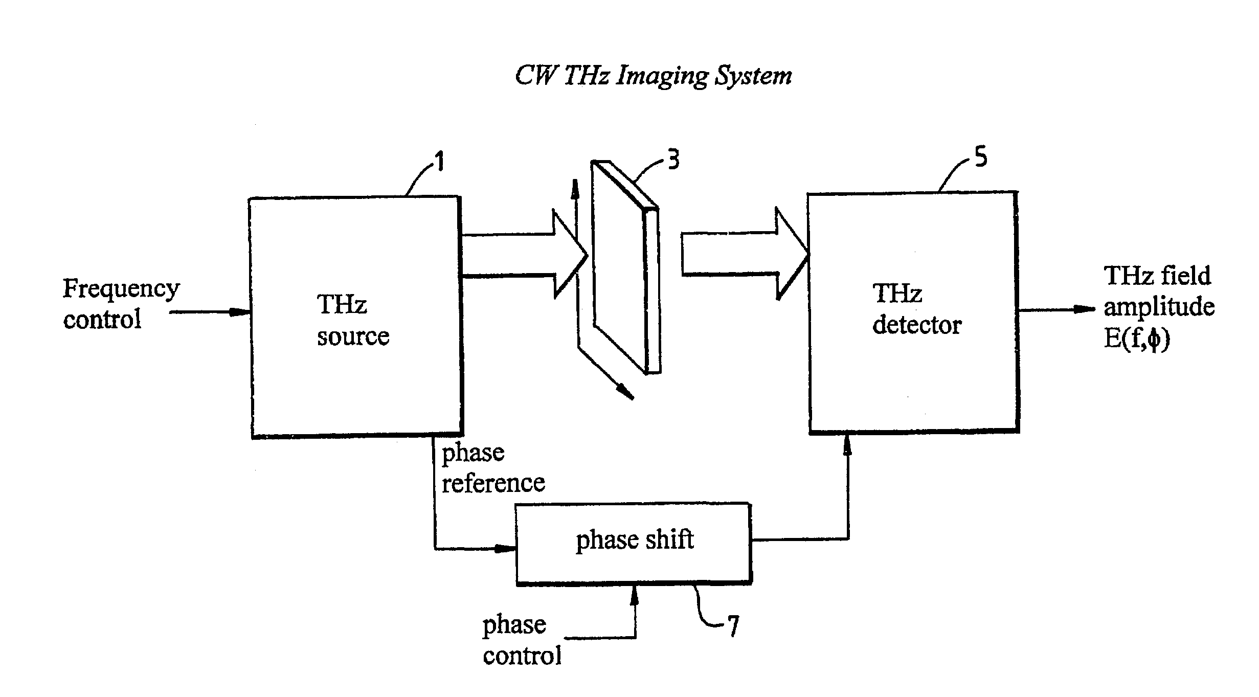
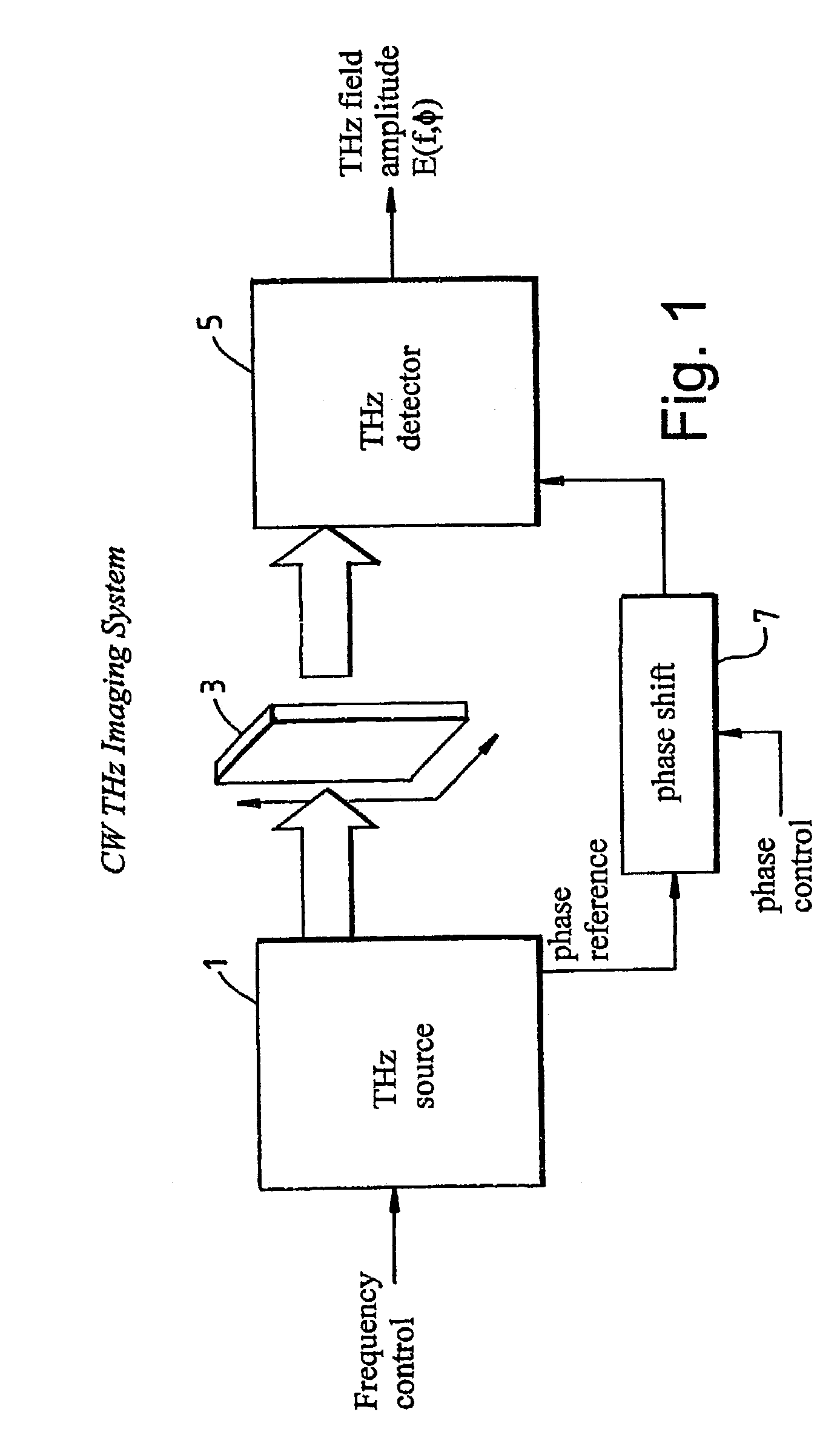
[0067]In the imaging system of FIG. 1, radiation is generated from THz generator 1. THz generator 1, generates terahertz radiation with a single frequency in the range from 0.025 THz to 100 THz. (Details of THz generator 1 will be described with reference to FIGS. 3 to 9.) The THz radiation emitted from the generator 1 irradiates sample 3.

[0068]Sample 3 is located on a stage (not shown), the stage is capable of moving sample 3 through the beam of radiation emitted from generator 1 in the x and y directions. The x and y directions being taken as two orthogonal directions which are substantially perpendicular to the path of the incident irradiating radiation from the source 1.

[0069]Sample 3 will both transmit and reflect radiation. In the specific example of FIG. 1, the sample is only shown to transmit radiation and only transmitted radiation will be detected. However, reflection measurements are possible.

[0070]The transmitted radiation is detected by detector 5. (Examples of the type...


PUM


Abstract

An apparatus and method for imaging a sample, the apparatus including a source for irradiating a sample with a beam of substantially continuous electromagnetic radiation having a frequency in the range 25 GHz to 100 THz; means for subdividing an area of the sample which is to be imaged into a two dimensional array of pixels; means for detecting radiation from each pixel wherein the detector is configured to detect a phase dependent quantity of the detected radiation which is measured relative to the radiation which irradiates the sample.

Description

BACK GROUND OF THE INVENTION[0001]1. Field of the Invention[0002]The present invention relates to the field of imaging apparatus and methods. More specifically, the present invention relates to imaging using frequencies in the range overlapping the infrared and microwave parts of the spectrum. This frequency range encompasses the so-called Terahertz (THz) frequency range and is often referred to as Terahertz radiation.[0003]2. Description of Related Art[0004]Recently, there has been considerable interest in THz pulse imaging (TPI) which is showing promising results for both medical and non-medical use. THz radiation is non ionising radiation. Therefore, it is believed to be medically safer than well established x-ray techniques. The lower power levels used (nW to μW) also suggest that heating effects are not problematic, as may be the case with microwaves for example.[0005]THz pulse imaging uses a plurality of frequencies within a single pulse in order to probe the frequency depende...

Claims


Application Information

Patent Timeline
IPC IPC(8): G06K9/00G01B11/06G01N21/17G01N21/35G01N21/47G02F1/37H01S5/343
CPCG01N21/4795G01N21/3581
Inventor ARNONE, DONALD DOMINICCIESLA, CRAIG MICHAELCOLE, BRYAN EDWARD
Owner TERAVIEW
Why Eureka
Try Eureka