Apparatus and method for reducing contamination of an image transfer device

a technology of image transfer device and apparatus, which is applied in the direction of electrographic process apparatus, corona discharge, instruments, etc., can solve the problems of oil layer, oil layer, airflow through or past the photoconductor surface, etc., and achieve the effect of reducing the contamination of the image transfer surfa

Active Publication Date: 2007-02-06
HEWLETT PACKARD DEV CO LP
View PDF11 Cites 13 Cited by
  • Summary
  • Abstract
  • Description
  • Claims
  • Application Information

AI Technical Summary

Benefits of technology

[0014]The invention described herein provides an apparatus and method for reducing contamination of an image transfer surface in an image transfer device. In one embodiment, the apparatus includes at least one charging device for charging the image transfer surface. An airflow control system is configured to ventilate the charging device and direct airflow in a direction substantially parallel to and spaced apart from the image transfer surface.

Problems solved by technology

Although an active airflow through the image transfer device is sometimes required or desired for ventilation, airflow through or past the photoconductor surface is problematic in long term use of the photoconductor surface.
In particular, active airflow is problematic because the airflow evaporates the submicron oil layer on the photoconductor surface and entrains oil vapors present above the oil layer, thereby effectively thinning the oil layer.
This increases the chance for dissolved residual materials to drop out of solution and polymerize on the photoconductor surface.
As contamination of the photoconductor increases over time, the print quality of subsequently printed images is reduced, and the useful life of the photoconductor surface is shortened.
However, effectively cleaning the photoconductor surface of all residual materials is very difficult, and some amount of residual material inevitably remains on the photoconductor surface.

Method used


Image

  • Apparatus and method for reducing contamination of an image transfer device
  • Apparatus and method for reducing contamination of an image transfer device
  • Apparatus and method for reducing contamination of an image transfer device

Examples


example

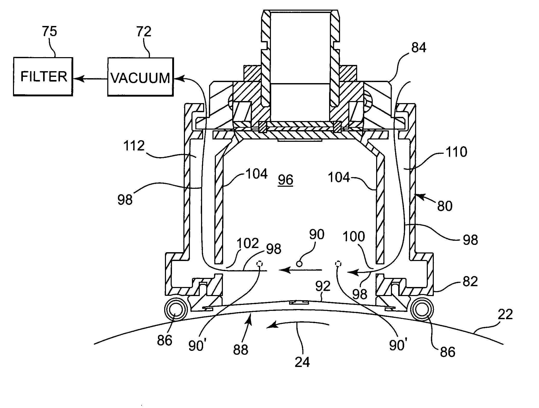
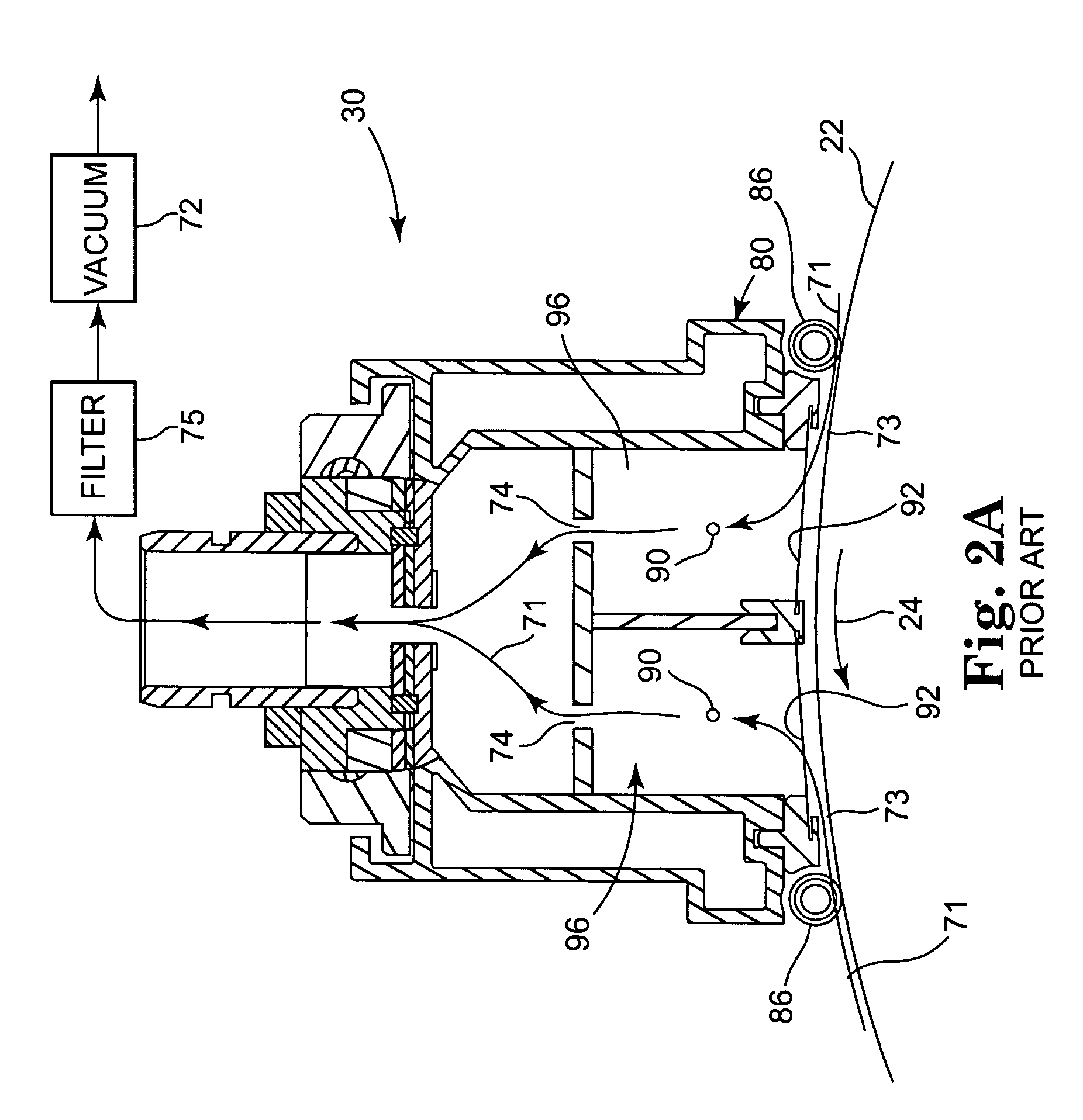
[0039]A liquid electrophotographic (LEP) printer was operated with a charging apparatus having an airflow control system like that illustrated in FIG. 2A for 100,000 printing cycles at 10% and 20% grayscale, and the dot area was measured at periodic intervals. Dot area is the estimated ink coverage of a tint patch, and is typically derived using an optical densitometer. The LEP printer was also operated for 100,000 printing cycles at 10% and 20% grayscale with a charging apparatus 30 having an improved airflow pattern like that illustrated in FIG. 3, and the dot area was measured at periodic intervals. The change in dot area for the prior art airflow pattern of FIG. 2A and the improved airflow pattern of FIG. 3 is illustrated in the graph of FIG. 5, where lines 150 and 152 indicate the prior art airflow pattern at 10% and 20% grayscale, respectively, and lines 154 and 156 indicate the improved airflow pattern at 10% and 20% grayscale, respectively. A decrease in dot area is indicati...


PUM


Abstract

An apparatus and method for reducing contamination of an image transfer surface in an image transfer device includes a charging device for charging the image transfer surface. An airflow control system ventilates the charging device and restricts airflow adjacent the image transfer surface.

Description

BACKGROUND OF THE INVENTION[0001]The present invention generally relates to image transfer technology and, more particularly, to an apparatus and method for reducing contamination of image transfer surfaces of image transfer devices during the printing process, and an image transfer device having the apparatus.[0002]As used herein, the term “image transfer device” generally refers to all types of devices used for creating and / or transferring an image in a liquid electrophotographic process, including laser printers, copiers, facsimiles, and the like.[0003]In a liquid electrophotographic (LEP) printer, the surface of a photoconducting material (i.e., a photoreceptor) is charged to a substantially uniform potential so as to sensitize the surface. An electrostatic latent image is created on the surface of the photoconducting material by selectively exposing areas of the photoconductor surface to a light image of the original document being reproduced. A difference in electrostatic char...

Claims


Application Information

Patent Timeline
Patent Type & Authority Patents(United States)
IPC IPC(8): G03G15/02G03G21/00G03G21/20
CPCG03G15/0258G03G2215/027
Inventor GILA, OMERLEE, MICHAEL H.CHANG, SEONGSIK
Owner HEWLETT PACKARD DEV CO LP
Why Eureka
Try Eureka