
Integrated interactive software visualization environment

Inactive Publication Date: 2007-02-06
IOWA STATE UNIV RES FOUND
View PDF25 Cites 199 Cited by
  • Summary
  • Abstract
  • Description
  • Claims
  • Application Information

AI Technical Summary

Benefits of technology

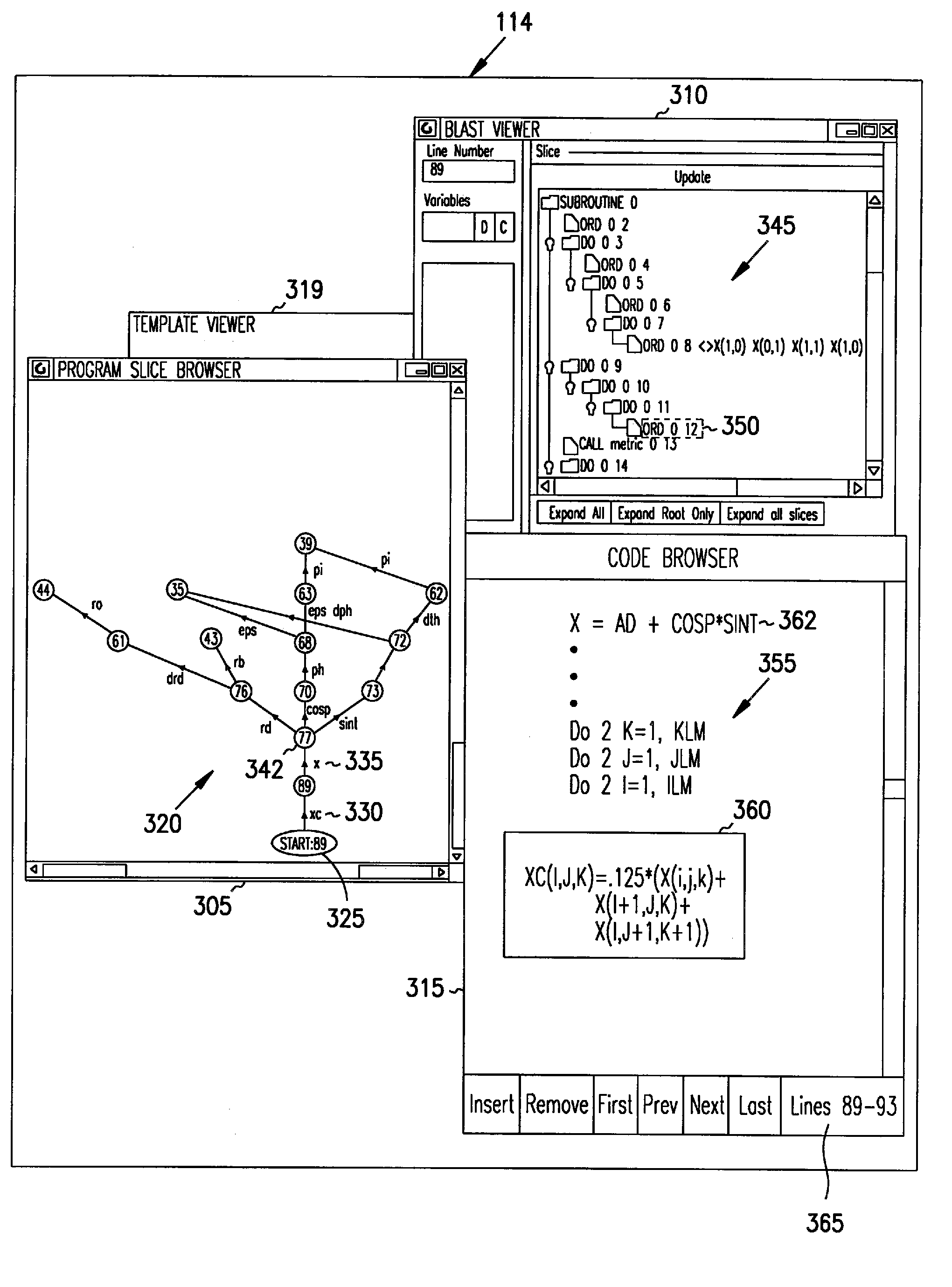
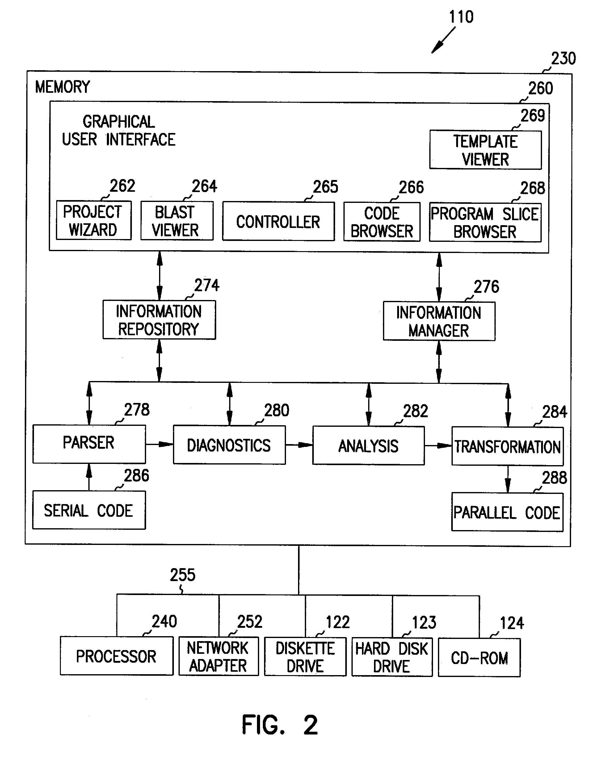
[0012]In another aspect, the invention encompasses a software environment for visualizing source code that includes a code browser, a block-level abstract syntax tree viewer, a program slice br

Problems solved by technology

As computers have become more advanced, the computer programs that operate and run on them have become much larger and more complicated.
Some computer programs have been written over the course of years, or even decades, and the people who originally designed and wrote them are no longer available.
Thus, it is often an arduous task to understand, let alone debug (find and correct errors in) large, complicated computer programs.
Prior products used a program slice simply as a sequence of program statements, which is a significant limitation because for a large program the program slice can be quite large and complicated, and it is not easy for a programmer to use it for the logical analysis necessary for program understanding and debugging.
For example, prior products do not provide a way to navigate through the program slice and visualize the structure of the program.
Prior products build control-flow and data-flow representations of a program a priori, and therefore might require prohibitively large amounts of storage and time when analyzing large programs.
These products do not support any mechanisms to deal with the large volume of analysis data and its complexity.
Existing tools do not provide any mechanism to visualize and analyze a program with respect to its high-level model.
These choices are critical, and without proper choices the debugging can be time consuming.
This is especially so in a case where the execution takes an extended period of time, and it is not practical to do many debugging trials.
For a small program, the user often logically analyzes the program and creates a hypothesis for debugging, which is very difficult to do for a large and complex program.

Method used


Image

  • Integrated interactive software visualization environment
  • Integrated interactive software visualization environment
  • Integrated interactive software visualization environment

Examples


Embodiment Construction

[0023]In the following detailed description of exemplary embodiments of the invention, reference is made to the accompanying drawings (where like numbers represent like elements) that form a part hereof, and in which is shown by way of illustration specific exemplary embodiments in which the invention may be practiced. These embodiments are described in sufficient detail to enable those skilled in the art to practice the invention, but other embodiments may be utilized and logical, mechanical, electrical, and other changes may be made without departing from the scope of the present invention. The following detailed description is, therefore, not to be taken in a limiting sense, and the scope of the present invention is defined only by the appended claims.

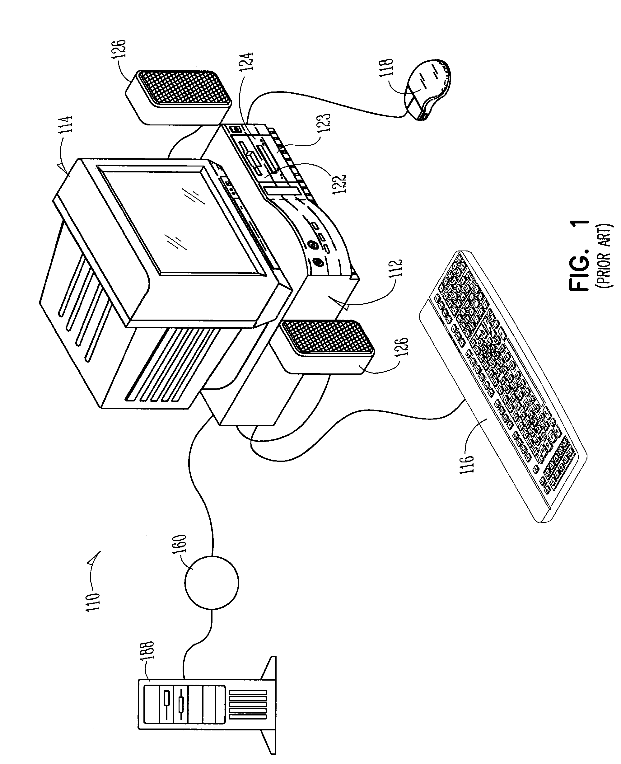
[0024]FIG. 1 depicts a pictorial example of a computer system that can be used to implement an embodiment of the invention. Computer system 110 is connected to remote server computer system 188 via network 160. In another embodiment...


PUM


Abstract

A method, system, apparatus, and program product for displaying a program slice diagram, which represents source code. The program slice diagram includes a directed graph that has multiple nodes and arcs connecting the nodes. Nodes can correspond to statements within a selected subroutine of the source code, variable references outside the subroutine, or calls made to other subroutines that are considered part of the program slice. Arcs represent data flow dependencies between the nodes. In another aspect, the invention encompasses a software environment for visualizing source code that includes a code browser, a block-level abstract syntax tree viewer, a program slice browser, and a template viewer. This software visualization environment is integrated, allows cross-referencing between its components, and is coupled with a performance visualization environment.

Description

STATEMENT AS TO RIGHTS TO INVENTIONS MADE UNDER FEDERALLY SPONSORED RESEARCH AND DEVELOPMENT[0001]Portions of the present invention were made with the support of the United States Government via a grant from the United States Environmental Protection Agency (EPA) under grant R-825206-01-0. The U.S. Government has certain rights in the invention.FIELD OF THE INVENTION[0002]This invention relates generally to computers and more particularly to slices of computer programs.COPYRIGHT NOTICE / PERMISSION[0003]A portion of the disclosure of this patent document contains material that is subject to copyright protection. The copyright owner has no objection to the facsimile reproduction by anyone of the patent document or the patent disclosure as it appears in the Patent and Trademark Office patent file or records, but otherwise reserves all copyright rights whatsoever. The following notice applies to the software and data as described below and in the drawings hereto: Copyright© Iowa State Un...

Claims


Application Information

Patent Timeline
IPC IPC(8): G06F9/44G06F9/45
CPCG06F11/3664
Inventor KOTHARI, SURAJ C.KRISHNASWAMY, ARAVINDNAMARA, YOGYDENG, YUNBO
Owner IOWA STATE UNIV RES FOUND
Learn More