Ergonomic shielding tool for processing a surface

a shielding tool and ergonomic technology, applied in the field of ergonomic shielding tools, can solve the problems of easy damage to the user's hand, easy to fall off, and easy to damage the user's hand, and achieve the effect of prolonging the use without fatigue or injury

Inactive Publication Date: 2007-02-13
STILES RONNIE J
View PDF28 Cites 12 Cited by
  • Summary
  • Abstract
  • Description
  • Claims
  • Application Information

AI Technical Summary

Benefits of technology

[0030]The invention herein is an ergonomic shielding tool (10) that can be held in one hand to define a boundary against which a surface is processed on one side and protected from processing steps on the opposite side. The invention achieves this utility by providing a handle (20) that is well-fitted for the human hand to allow prolonged use without fatigue or injury to the user. In use, the invention simultaneously shields one section of a surface while exposing the second section of the same surface for treating the invention herein can be used in any number of applications wherein a surface is being treated in sections. The inventors do not wish to be limited by one particular use of the invention, but the tool is readily adapted for use in guiding a paint scraper, setting boundaries for paint or other chemicals to be applied to a surface, or other mechanisms by which a surface is changed in some fashion requiring a controlled exposure of different portions of the surface. The inventor herein describes the tool and its uses in four embodiments. The first embodiment is a one-piece ergonomic shielding tool (10) with a straight edge (13) for dividing a surface into two regions and a curved handle (20) for ergonomic hand-held use. The second embodiment shows a one-piece ergonomic shielding tool (10)formed in a substantially planar sheet of material. The tool is composed of a straight guide edge (13) at one end of a guide panel (15), a shielding panel (15) extending at an angle from the guide panel (17), and an ergonomically curved handle (20) extending from the guide panel (15). The third embodiment is a combination of the ergonomic shielding tool (10) and a paint removal apparatus (30) for use in scraping paint from one section of a surface and leaving another section protected from the paint removal process. The fourth embodiment is a method of removing dried paint from a surface and utilizing the ergonomically enhanced shielding tool (10) according to the method of the invention.

Problems solved by technology

A glass surface, such as a window pane held in place by a frame, often proves to be one of the more difficult surfaces to treat.
Regardless of the careful painting methods involved, a painter often finds that paint spills off the frame and covers part of the window.
Dried paint on a window is typically an undesirable result.
The taping method is not always the answer, however.
First of all, applying tape to all of the edges of a window pane may be just as time consuming and difficult as scraping the glass to rid excess paint.
Second, depending on the width of the tape, there is no guarantee that the tape will completely protect the glass.
Third, tape will only stick to glass by use of an adhesive, and this adhesive often remains on the glass after removing the tape.
If the tape is applied unevenly, then the window frame may be painted unevenly as well, resulting in a sloppy edge.
Scraping window panes of excess paint can be a time consuming and arduous task.
A razor blade is sufficiently sharp for the job, but a razor blade is very difficult to use by hand.
The small size of a razor blade makes it difficult to use for extended periods of time without exhausting or even injuring the user's hand.
The razor blade is of limited applications, therefore, because the razor blade is not conducive for use on large windows or a great number of windows that need to be scraped quickly.
The painting industry has recognized the inherent problems incurred when scraping paint from surfaces.
These tools, however, often suffer the drawback of being uncomfortable to use for extended periods due to handles that do not easily fit the user's grip.
Fabrication of tools with many pieces is difficult because individual components must be linked together in manufacturing the scraper.
First, many tools are too large and cumbersome for detailed work that requires precise processing of one area of a surface while simultaneously leaving a second area of the surface unchanged.
Commonly available tools are inappropriate for these types of applications in which a user seeks precision and detail.
Another problem in commonly available tools for surface processing is that of ergonomics.
Industries have only recently begun to study the impact that poorly designed handles have on the user's grip, comfort, and associated endurance in using the tool.
Prior filed patent applications and previously issued patents show that presently available tools are deficient in regard to the two most problematic areasuse on surfaces requiring precise detail and use for extended periods without fatigue caused by a poorly designed handle.
A simple arch of metal or other material, however, has the significant drawback of causing discomfort or injury to the user after extended periods.
The uniform thickness of the arch would eventually wear on the user's hand, and the article offers no significant means of avoiding that discomfort.
This assembly adds to the complexity, and therefore the cost, of the resulting tool.
These known embodiments, however, require excessive assembly steps to fabricate the final tool.
Certain of the handles are also limited in their applications due to the grips that the handles allow within a user's hand.
The second problem discussed herein is the continued need for surface processing tools that may be used in applications requiring precise detail work.
The Olson '609 guide is made of a very thin sheet and provides no comfortable means of gripping the guide.
The Olson '609 apparatus, therefore, suffers the previously discussed problem of user fatigue or even injury after prolonged use.
The only means for holding the Olson '609 guide is by pinching the guide between two fingers, a position that is not ergonomically beneficial to the user's hand.
This assembly requires more effort and increases the cost of manufacturing a complete tool.
Tools available in today's marketplace also lack optimal utility in applications that require extra degrees of precision in processing or treating a surface.

Method used


Image

  • Ergonomic shielding tool for processing a surface
  • Ergonomic shielding tool for processing a surface

Examples


first embodiment

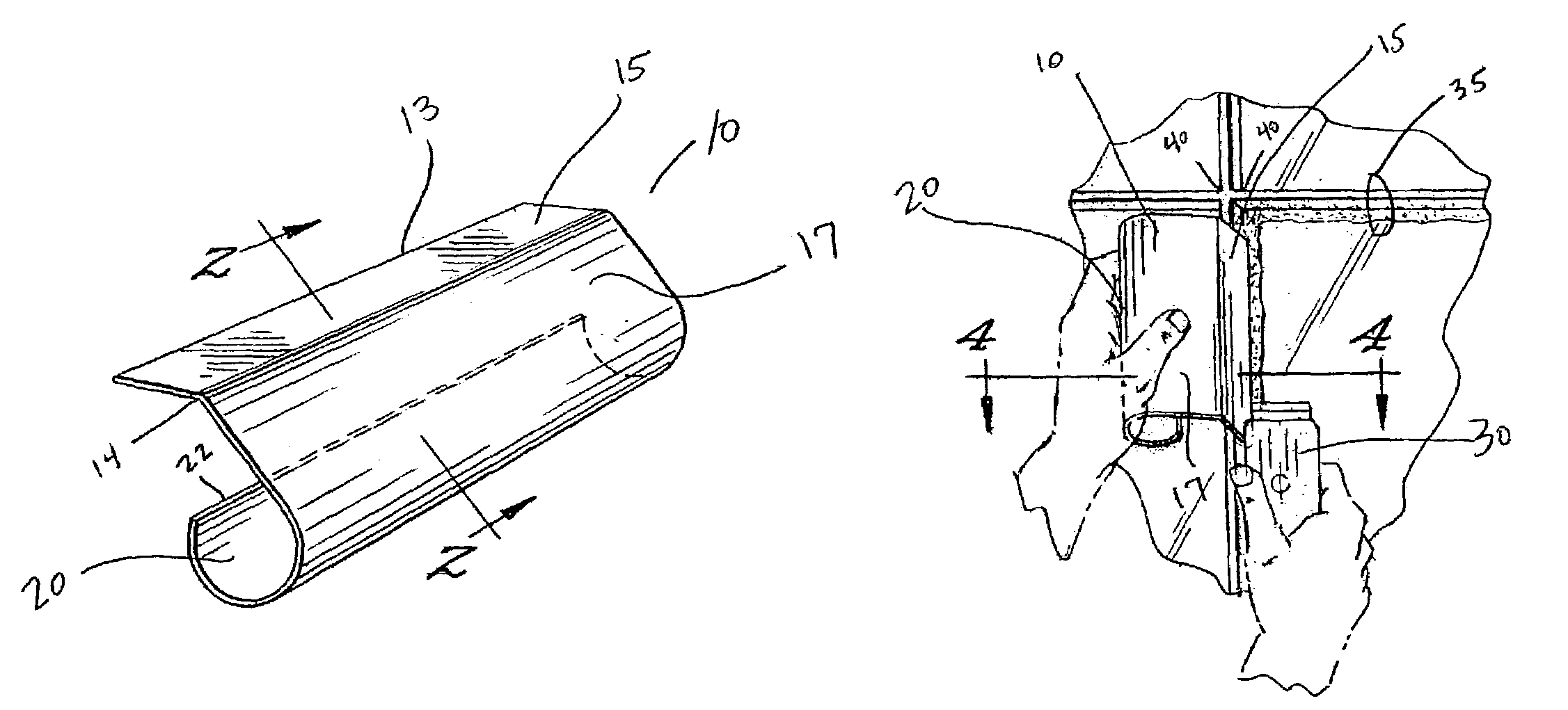
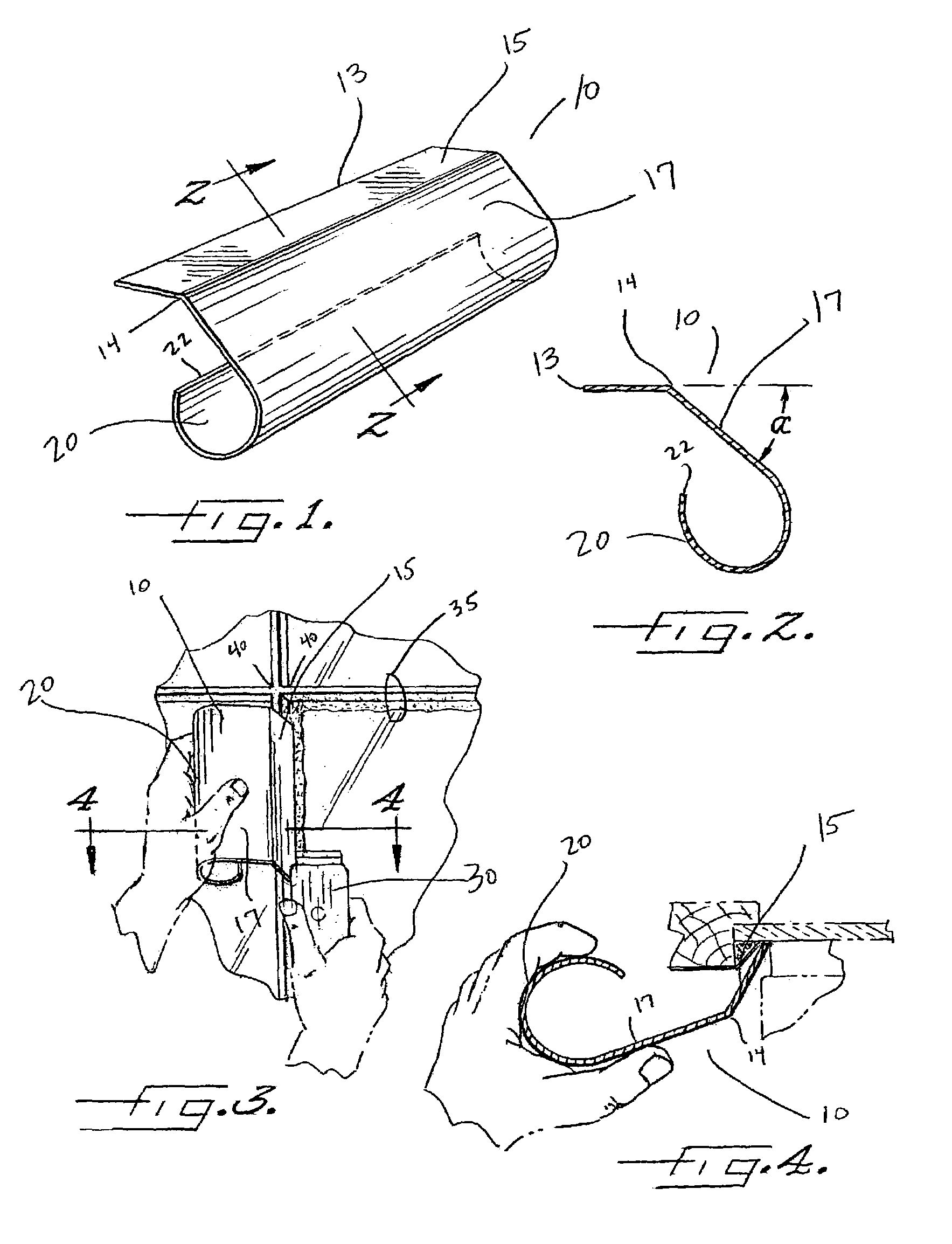
[0036]In a first embodiment, the tool includes a single-piece body (10) of substantially uniform thickness with a straight edge (13) at a first end of the body. The user places the straight edge (13) against a surface to separate the surface into first and second regions on opposite sides of the straight edge. These separate portions of the surface may be distinctly processed, depending on the use at hand.

[0037]The body of the tool (10) may be made of a substantially planar sheet of material of substantially uniform thickness. The selected material can be metal, plastic, rubber, or any other convenient material that is formable into the desired shape with a straight edge (13) at a first end of the sheet. A sheet of formable material may be conveniently bent and curved to form the invention claimed here. Alternatively, common molding techniques are equally pertinent to fabricating the tool claimed herein. Shaping a single sheet of a material, such as a metal, is the simplest means of...

second embodiment

[0047]The second embodiment includes a single-piece body (10) having a substantially rectangular guide panel (15) with a guide edge (13) at one end. The guide edge (13) is straight, and in use, the guide edge (13) is placed flush against a surface. The guide edge (13) against a surface separates the surface into two regions on opposite sides of the guide edge (13).

[0048]The tool (10) further includes a shield panel (17) extending at an angle (a) from the guide panel (15), opposite the guide edge (13), to protect and cover a portion of the surface on one side of the guide edge (13). The portion of the surface on the opposite side of the guide edge (13) is exposed for further processing.

[0049]The second embodiment of the tool further includes a curved handle (20) extending from the shield panel (17), opposite the guide panel (15), for gripping the body (10) and holding the guide edge (13) against a surface. In use, when the straight guide edge (13) is flush against a surface, the shie...

fourth embodiment

[0069]The inventors herein also describe and claim a method of removing paint from a window held in place by a painted frame (35). This fourth embodiment of the claimed invention is an ergonomic method of removing dried paint from a window while holding an ergonomic shielding tool (10) in one hand.

[0070]The shielding tool (10) has a one-piece body with a substantially rectangular guide panel (15) with a straight guide edge (13) at one end, a substantially planar shield panel (17) extending at an angle from the guide panel (15) opposite the guide edge (13), and a rounded handle (20) extending from the shield panel (17) opposite the guide panel (15). According to the method herein, the user grips the shielding tool (10) so that the rounded handle (20) extends along the palm of the user's hand.

[0071]The user places the guide edge (13) of the shielding tool against a window so that the shield panel (17) covers a first portion of the window, and a second portion of the window remains unc...


PUM


Abstract

The invention is a one-piece ergonomic shielding tool that can be held in one hand to define a boundary against which a surface is processed on one side and protected from processing steps on the opposite side. The invention achieves this utility by providing a handle that is ergonomically fitted for the human hand to allow prolonged use without fatigue or injury to the user. The invention includes a straight edge, or guide edge, for dividing a surface into two regions and a curved handle for ergonomic hand-held use. The ergonomic shielding tool and a paint removal apparatus are useful in combination for scraping paint from one section of a surface and leaving another section protected from the paint removal process. The tool is adapted for use in a method of removing dried paint from a surface in a precise manner.

Description

BACKGROUND OF INVENTION[0001]The present invention relates to an ergonomic hand-held tool (10) with a straight edge (13) that is useful for dividing a surface into two regions an exposed region and a shielded regionon either side of the straight edge. The tool facilitates the application or removal of material on the exposed region of a surface while simultaneously protecting the shielded region.[0002]The application or removal of material from a surface takes place in wide variety of scenarios. A few well known instances include painting walls or other structures, staining furniture to a desirable color, and removing rust from metal objects. Industrial applications often require even more precise surface processing, such as using caustic chemicals to treat specific areas of a surface while leaving a second area unchanged. These types of precise surface processing methods require means of distinguishing from a surface area to be processed and a surface area to be left unchanged. The...

Claims


Application Information

Patent Timeline
Patent Type & Authority Patents(United States)
IPC IPC(8): A47L13/02A47L13/50B05B15/04
CPCB05B15/0475B05B12/28
Inventor STILES, RONNIE J.
Owner STILES RONNIE J
Why Eureka
Try Eureka