Split shroud exhaust nozzle

a technology of exhaust nozzle and shroud, which is applied in the direction of jet flaps, marine propulsion, vessel construction, etc., can solve the problems of not being able to efficiently operate, reducing operating efficiency, increasing cost, weight, maintenance effort, etc., and achieves the effect of decreasing diameter and increasing diameter

Active Publication Date: 2007-02-13
GENERAL ELECTRIC CO
View PDF35 Cites 84 Cited by
  • Summary
  • Abstract
  • Description
  • Claims
  • Application Information

AI Technical Summary

Problems solved by technology

Fixed nozzles do not kinematically change their geometry and thus are not designed to operate efficiently over a wide range of nozzle pressure ratios (P8 / Pamb).
Because of the overlapping flap & seal structure, there are numerous leakage paths which reduce operating efficiency, and the large number of parts required increases cost, weight, and maintenance effort, and decreases reliability.
A8 relationship will not match the engine cycle demands optimally and thus will not deliver peak nozzle performance at certain key operating points.
Although prior art overlapping flap and seal nozzles exist which enable independent A9 and A8 control they still suffer from excessive complexity and sealing difficulties.

Method used


Image

  • Split shroud exhaust nozzle
  • Split shroud exhaust nozzle
  • Split shroud exhaust nozzle

Examples


Embodiment Construction

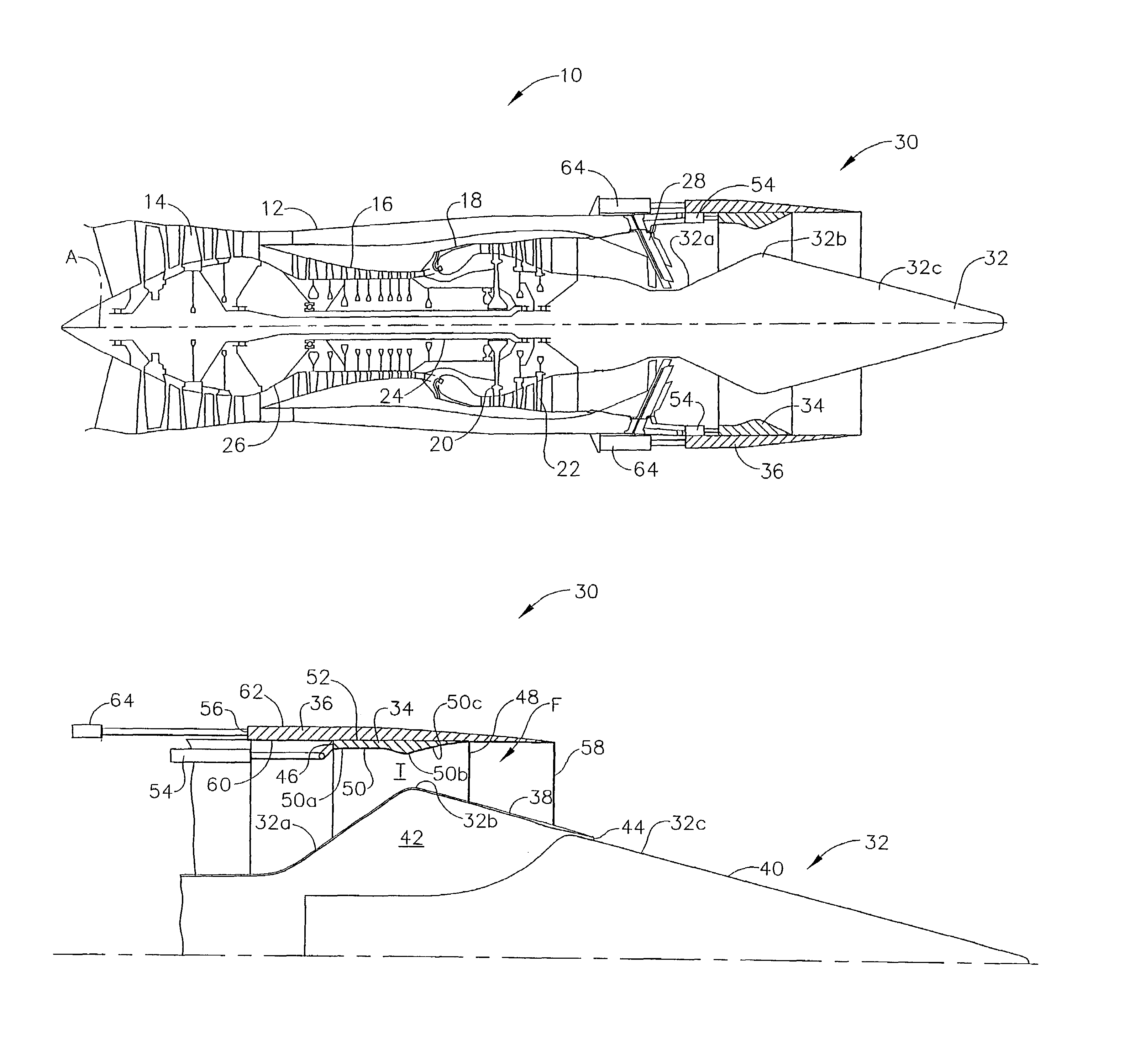
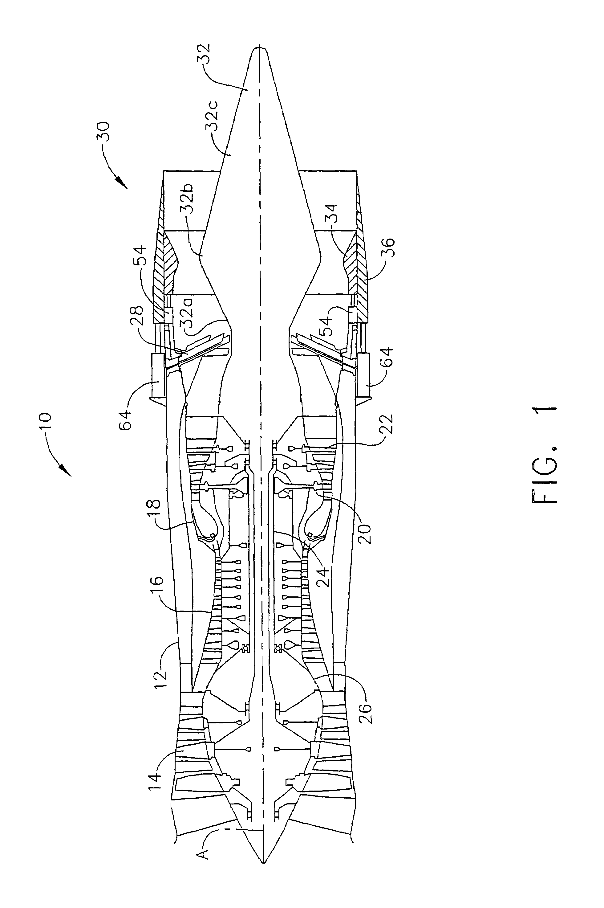
[0022]Referring to the drawings wherein identical reference numerals denote the same elements throughout the various views, FIG. 1 illustrates a representative gas turbine engine, generally designated 10. The engine 10 has a longitudinal center line or axis A and an outer stationary annular casing 12 disposed concentrically about and coaxially along the axis A. The engine 10 has a fan 14, compressor 16, combustor 18, high pressure turbine 20, and low pressure turbine 22 arranged in serial flow relationship. In operation, pressurized air from the compressor 16 is mixed with fuel in the combustor 18 and ignited, thereby generating combustion gases. Some work is extracted from these gases by the high pressure turbine 20 which drives the compressor 16 via an outer shaft 24. The combustion gases then flow into the low pressure turbine 22, which drives the fan 14 via an inner shaft 26. An afterburner 28, or augmentor, may optionally be provided for increasing the thrust of the engine 10 a...


PUM


Abstract

A variable geometry convergent-divergent nozzle for a gas turbine engine includes a centerbody extending rearward along a longitudinal axis of the engine which has a throat section of increased diameter. An inner shroud surrounds the centerbody and cooperates with the centerbody to define the throat of the nozzle. An outer shroud surrounds the inner shroud and cooperates with the centerbody to define the exit area of the nozzle. Both shrouds are independently translatable to provide independent control of the nozzle throat area and the nozzle expansion ratio.

Description

STATEMENT REGARDING FEDERALLY SPONSORED RESEARCH AND DEVELOPMENT[0001]The U.S. Government may have certain rights in this invention pursuant to contract number MDA972-01-3-0002 awarded by DARPA.BACKGROUND OF THE INVENTION[0002]This invention relates generally to nozzle for gas turbine engines and more particularly to a variable geometry convergent-divergent nozzle.[0003]Exhaust systems for gas turbine engines which operate over a wide range of pressure ratios (i.e. nozzle throat pressure / ambient pressure or “P8 / Pamb”) require variable geometry in order to adjust the nozzle throat area (“A8”) to meet the demands of the engine cycle, and adjust the nozzle expansion ratio (i.e. nozzle exit area / nozzle throat area or “A9 / A8”) in order to attain good performance at the various operating points.[0004]Prior art exhaust nozzles include fixed exhaust systems typical of commercial subsonic engines, and variable exhaust nozzles typical of supersonic military aircraft which also use afterburner...

Claims


Application Information

Patent Timeline
Patent Type & Authority Patents(United States)
IPC IPC(8): B63H11/00B64G9/00F02K9/00B64G99/00F02K1/08
CPCF02K1/09F02K1/386F05D2250/311F05D2250/11Y02T50/671Y02T50/60
Inventor RENGGLI, BERNARD JAMES
Owner GENERAL ELECTRIC CO
Why Eureka
Try Eureka