Powered nailing machine

a gas-driven nailing machine and gas-driven technology, which is applied in the direction of nailing tools, manufacturing tools, stapling tools, etc., can solve the problems of deformation or breakage of the contact member and contact arm in some cases, accident may occur, and the nail driven portion of the work is difficult to be seen, so as to improve the visibility of the driven portion of the work, reduce the weight of the nose, and improve the operation efficiency

Inactive Publication Date: 2007-02-13
MAX CO LTD
View PDF19 Cites 25 Cited by
  • Summary
  • Abstract
  • Description
  • Claims
  • Application Information

AI Technical Summary

Benefits of technology

[0008]The problem of the present invention is to provide a power driven nailing machine capable of preventing the nailing machine from being erroneously operated due to the contact of the contact member, which forms a starting unit, with the work or the operator's inadvertent operation of the machine, and capable of easily carrying out the removal of the nail which gets clogged in the discharge port.
[0013]The contact member is provided at a free end portion of the discharge port, and the nose extension is formed on only the free end portion of the nose so as to cover this contact member. This enables the outer dimensions of the nose to be set small, the visibility of the driven portion of the work to be thereby improved, and the operation efficiency to be also improved. Moreover, since the contact member and the free end portion of the discharge port are enclosed with the cover member made integral with the nose, the contact member and free end portion of the discharge port can be protected against a shock occurring when the tool drops. Even when a sufficient strength is given to the nose, the weight thereof does not increase greatly, so that the weight of the nose can be reduced with the operation efficiency not spoiled.
[0014]The upper portion of this nailing machine except the free end portion of the nose is formed identically with that of a regular nailing machine. Therefore, it becomes possible to form an opening in a front portion of the nose, and provide a latch mechanism and the like for fixing a driver guide detachably to the nose so as to close this opening. This enables the nailing machine to be formed so that an operation for removing the nail when the inside of the discharge port is clogged therewith from the opening formed in the front portion of the nose can be carried out.

Problems solved by technology

Therefore, if the contact member and contact arm are made to contact the work and the like in such a case when the machine is carried, or if the machine is made to drop by mistake, the contact member and contact arm is deformed or broken in some cases.
In addition, the contact member and contact arm may be inadvertently operated by the hand of an operator or by the work when the contact member and contact arm inadvertently engage therewith.
Therefore, there is a possibility that an accident may occur.
This causes the nail driven portion of the work to become difficult to be seen, and a nail driving operation for a narrow portion of the work to become impossible.
Therefore, the nail removing operation carried out when the discharge port gets clogged with nails takes much time.
However, since the discharge port as a whole is moved, an operation of a timing for supplying a nail from a magazine to the inside of the discharge port is complicated, so that the construction of parts also becomes complicated.
Therefore, a work and the hand of the operator touch the outer surface of the link member to cause the nailing machine to be broken or erroneously operated.

Method used


Image

  • Powered nailing machine
  • Powered nailing machine
  • Powered nailing machine

Examples


Embodiment Construction

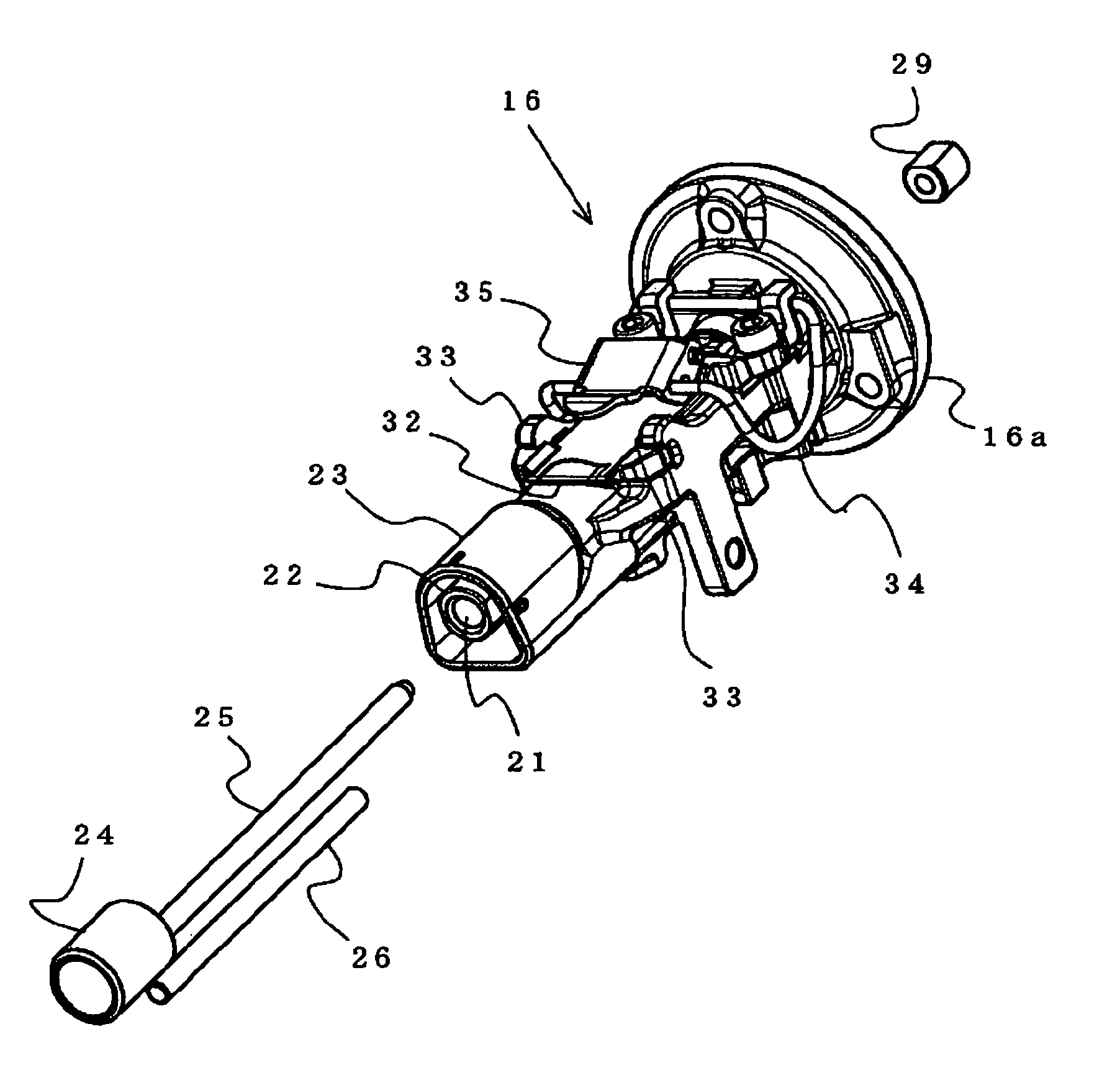
[0024]The present invention has achieved its object of preventing the contact member from touching the work or the fingers of an operator and the like of the operator to cause the nailing machine to be inadvertently operated, by rendering it possible not to spoil the visibility of the free end portion of the nose, and to carry out the nail removing operation easily when the nose gets clogged with nails.

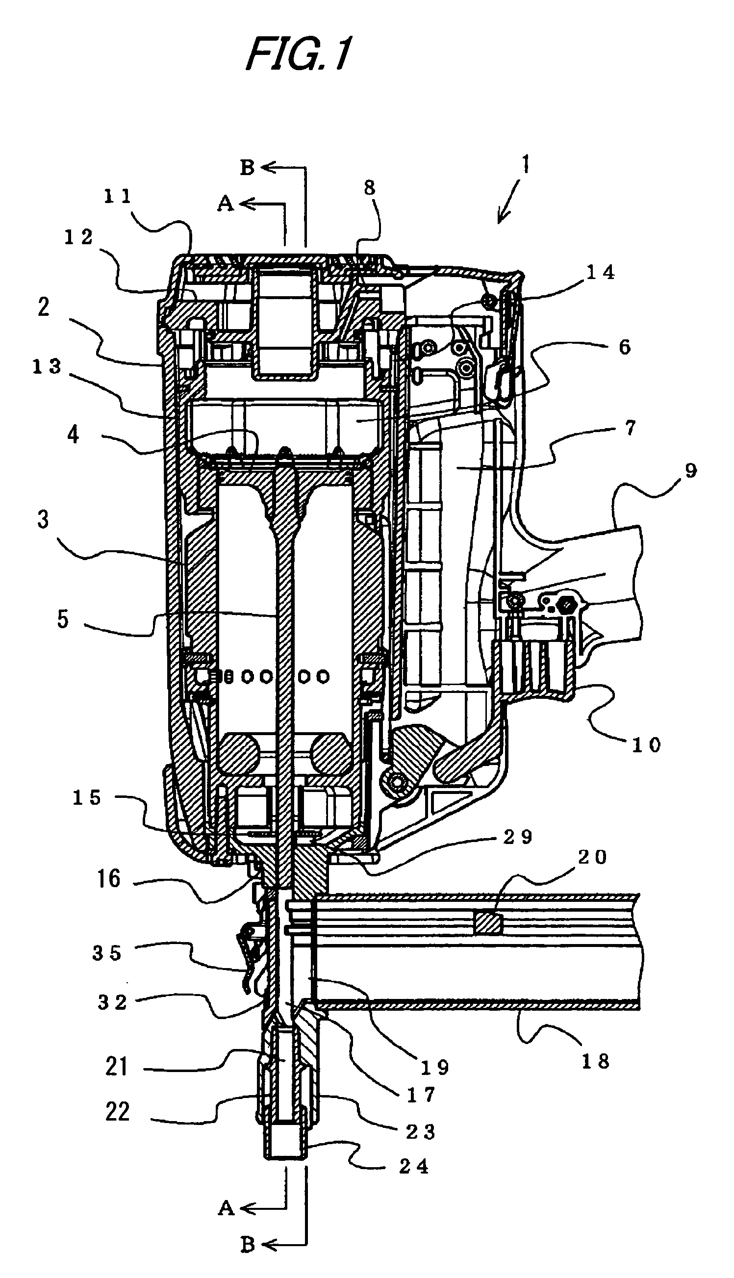
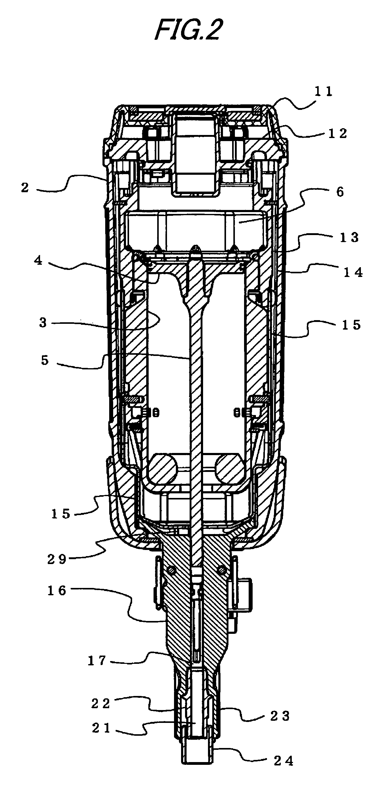
[0025]The drawings show a combustion gas-driven nailing machine as an example of the power driven nailing machine showing an embodiment of the present invention. As shown in the longitudinally sectioned side elevation of FIG. 1, a combustion gas-driven nailing machine 1 has a cylinder 3 in a housing 2, and a piston 4 to a lower surface of which a driver 5 for striking a nail is joined is held slidably in this cylinder 3. At an upper end of the cylinder 3 on which an upper surface of the piston 5 is exposed, a combustion chamber 6 is formed. The piston 4 is driven in the cylinder 3 wit...


PUM

PropertyMeasurementUnit
pressureaaaaaaaaaa
timeaaaaaaaaaa
strengthaaaaaaaaaa

Abstract

The guide rods 25, 26 extending straight along the discharge port 17 are fixed to the contact member 24, and this contact member 24 is retained slidably on the nose 16 via the guide rods 25, 26. The nose extension 23 is formed at the free end of the discharge port 17 so as to be integral with the nose 16 so that the nose extension covers the outer circumferential surface of the discharge port 17. The contact member 24 is held in the annular space formed between the nose extension 23 and discharge port 17, the contact member 24 being provided so as to project from free end of the nose extension.

Description

TECHNICAL FIELD[0001]The present invention relates to a combustion gas-driven nailing machine for striking a nail or a pin into a work, such as a concrete and a wooden material, by a driver connected to a piston by power-driving the piston by a pressure of a combustion gas generated by burning a combustible gas or by a pressure of compressed air; and a power driven nailing machine for striking the nail or the pin into the work by a driver connected to a piston by driving the piston in a cylinder by introducing compressed air into the cylinder holding the piston.BACKGROUND ART[0002]A combustion gas-driven nailing machine is known which is adapted to strike a nail into a steel plate or a concrete by a driver connected to a piston, by injecting a combustible gas into a closed combustion chamber and forming a mixed gas of the combustible gas and air in the combustion chamber, igniting the mixed gas and burning the same, imparting a high-pressure combustion gas thus generated in the comb...

Claims


Application Information

Patent Timeline
Patent Type & Authority Patents(United States)
IPC IPC(8): B25C1/04B25C1/08B25C7/00B25C1/18
CPCB25C1/188B25C1/008B25C1/08B25C11/00B27F7/09
Inventor OSUGA, SATOSHITANAKA, HIROSHIMURAYAMA, KATSUHIKO
Owner MAX CO LTD
Why Eureka
Try Eureka