

Positioning aid
a technology of positioning aids and shutters, applied in the direction of mould fastening means, machine supports, domestic objects, etc., can solve the problems of inability to use in flexible manner, entail rather high expenditure of known positioning aids, and achieve the effect of reliably anchoring in the shutters
- Summary
- Abstract
- Description
- Claims
- Application Information
AI Technical Summary
Benefits of technology
Problems solved by technology
Method used
Image

Examples
second embodiment
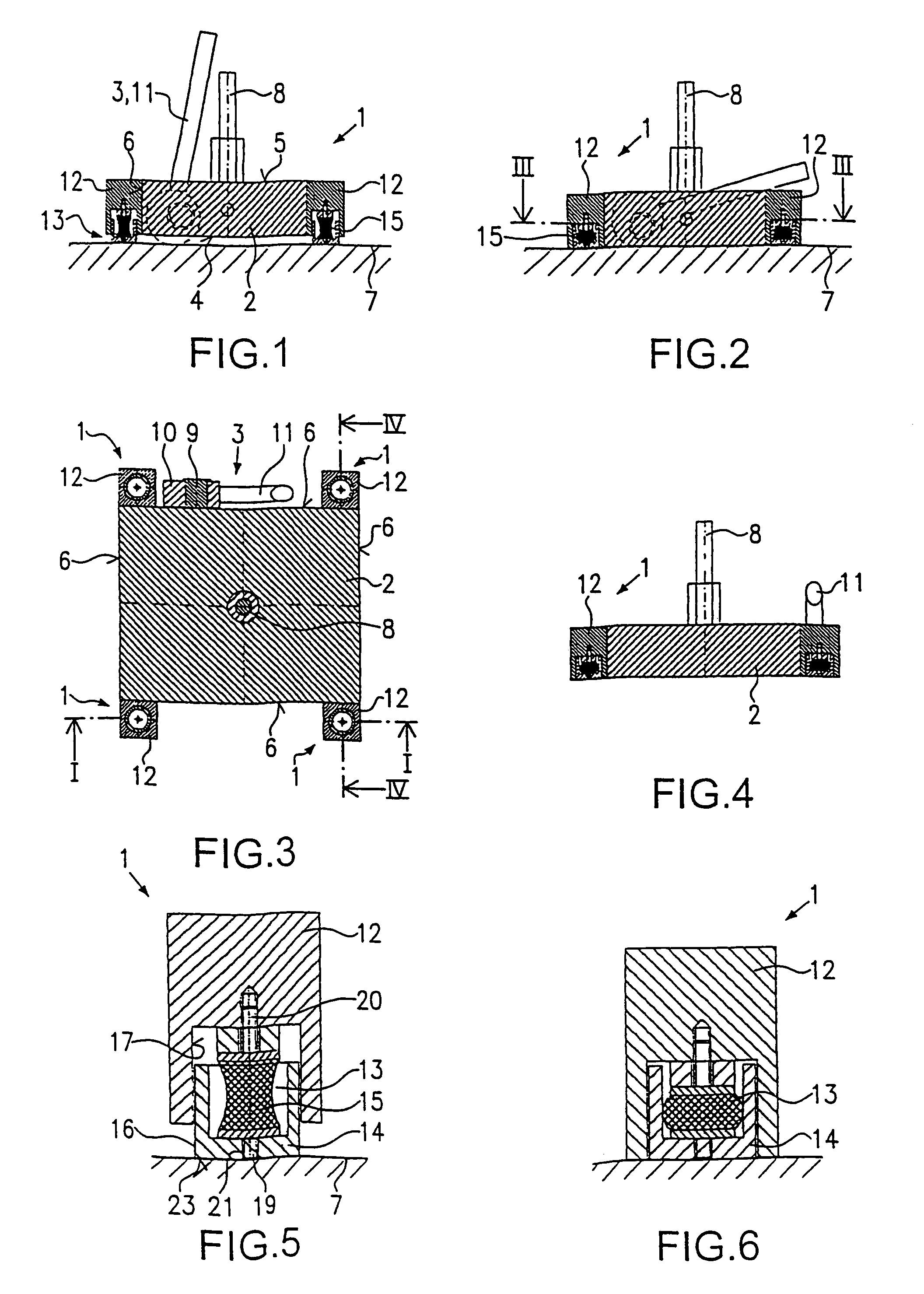
[0092]In the second embodiment, compression springs 24 made of steel or of plastic material are used instead of the spring elements 18. In FIG. 7, the retaining device with the support unit is shown in the condition in which the magnetic device 2 occupies the position of non-use. In FIG. 8, the magnetic device 2 occupies the position of use, so that the compression springs 24 are compressed. The rest-on means 14 is provided with a cover 25 having a hole 26 through which a rod-shaped member 27 extends, the rod-shaped member 27 having a stop 28 provided thereon. The rod-shaped member 27 is fixedly attached to the retaining device 12 by means of a screw connection. The stop 28, together with the cover 25, prevents the rest-on means 14 from becoming detached from the retaining device 12.
third embodiment
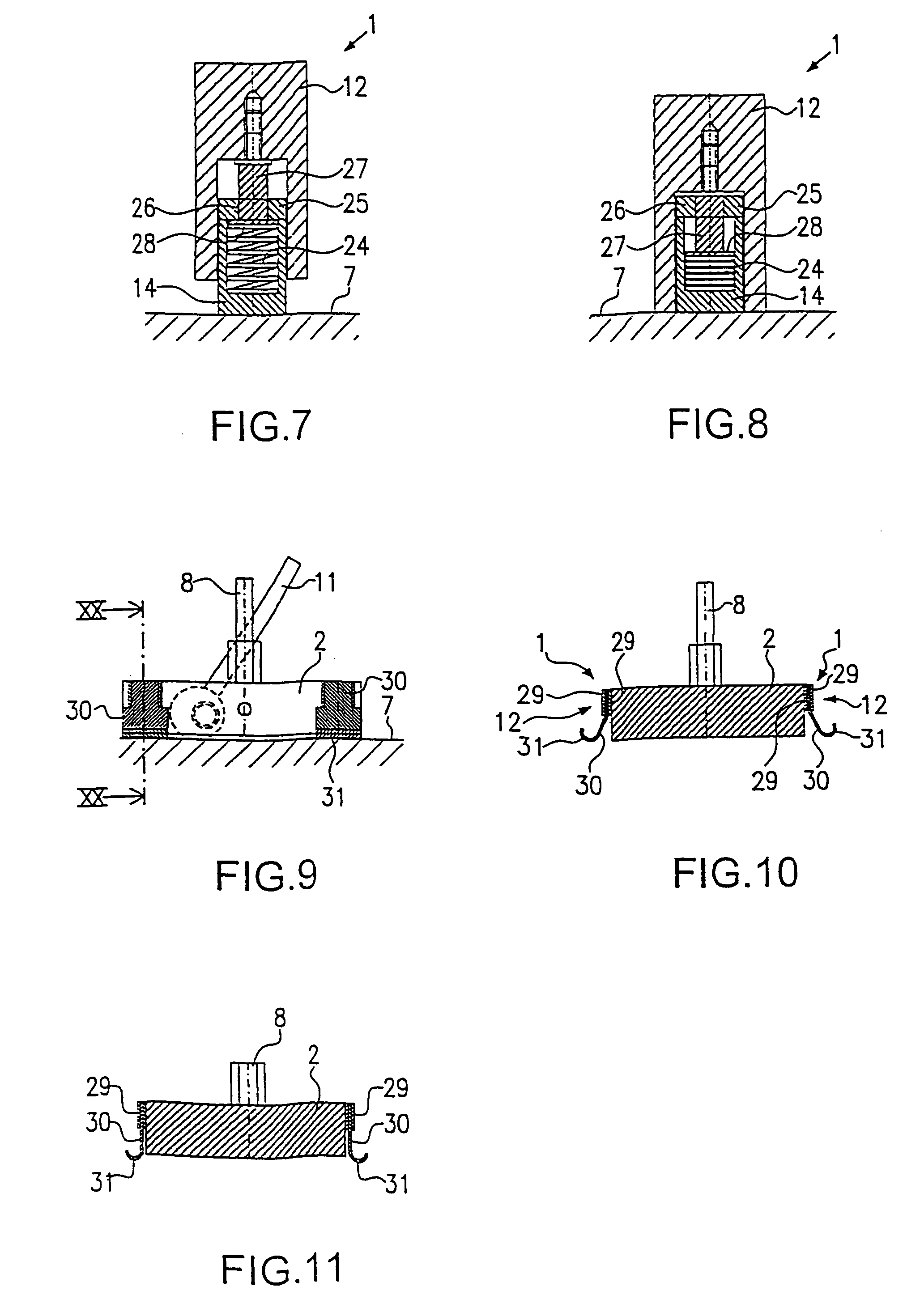
[0093]FIGS. 9, 10 and 11 describe the present invention. Also in this case, identical components are designated by identical reference numerals so as to avoid repetitions. Only the differences will be explained.
[0094]In contrast to the first embodiment, the retaining device 12 of the third embodiment comprises plate-shaped elements 29, which are attached to the magnetic device 2 and which accommodate between them a spring steel sheet 30 that extends vertically towards the shuttering support 7. As can be seen from FIGS. 10 and 11, end sections 31 of said spring steel sheets are laterally spread when the magnetic device is being transferred from its position of non-use to its position of use according to FIG. 10. Due to this deformation, they produce the necessary lifting force. In so doing, the end sections 31 slide on the shuttering support 7. In the position of non-use, the retaining device rests via the respective end sections 31 of the spring steel sheets 30 on the shuttering sup...
fifth embodiment
[0097]FIGS. 16 and 17 show a fifth embodiment, which is provided with retaining elements 34 as well, but in the case of which the connection plates are replaced by retaining bridges 37 which interconnect two respective retaining devices 12. An additional mounting plate 38 extends on the upper side 5 of the magnetic device 2 along a certain section thereof and can be connected to the magnetic device 2 via a hole 39 and a screw 40. Said screw 40 is located on the upper side 5 of the magnetic device 2. Due to the structural design of the retaining bridge 37 and of the retaining devices 12, the retaining element 34 is in large-area contact with the associated side face 6 of the magnetic device 2.
[0098]Also in this case compression springs are used as spring elements.
PUM
| Property | Measurement | Unit |
|---|---|---|
| Force | aaaaa | aaaaa |
| Shape | aaaaa | aaaaa |
| Elasticity | aaaaa | aaaaa |
Abstract
Description
Claims
Application Information