High-performance absorbent structure

a high-performance, absorbent core technology, applied in the field of absorbent cores, can solve the problems of cellulose material being generally not available in preformed sheets, affecting the effect of cellulose material availability, and small effective pore siz

Inactive Publication Date: 2007-02-13
BUCKEYE TECH INC
View PDF53 Cites 19 Cited by
  • Summary
  • Abstract
  • Description
  • Claims
  • Application Information

AI Technical Summary

Benefits of technology

[0017]The present invention relates to an absorbent structure having wet integrity greater than about 4.0 mN / gsm, softness greater than 8.0 / J, pliability greater than about 70 / N, and providing a substantially dry liquid-accepting surface after receiving a quantity of liquid. The structure includes an upper ply having an upper fluid receiving surface and a lower surface and including a top stratum including synthetic matrix fibers bonded with a binder, the matrix fibers having length from about 2 to about 15 mm; a middle stratum in fluid communication with the top stratum, the middle stratum including natural fibers, superabsorbent particles and a binder; and a bottom stratum in fluid communication with the middle stratum, the bottom stratum including natural fibers and a binder. The structure also includes a lower ply in fluid communication with the upper ply, the lower ply having an upper surface and a lower surface and including at least one stratum including natural fibers, superabsorbent polymer particles, and a binder, wherein the lower surface of the upper ply has a surface area less than about 80% of the upper surface area of the lower ply.

Problems solved by technology

However, higher density cores do not absorb liquid as rapidly as lower density cores because densification of the core results in a smaller effective pore size.
Multiple layer absorbent core designs involve a more complicated manufacturing process.
Such cellulose material is generally not available in preformed sheet form because it exhibits insufficient web strength, owing to its lack of interfiber bonding or entanglement, to be unwound or unfestooned directly onto and handled in absorbent pad-making equipment.
However, these absorbent structures are often inefficient in cases where a demand is for acquisition and absorption of high amounts or a surge of body fluids.
In these cases, a single sheet absorbent material often is not sufficient to fully utilize the absorbent core because the liquid is not distributed in the structure along the length of the absorbent core.
As a result, regions of the absorbent core remain unused.
However, such bonded materials provide a relatively stiff core which often does not conform well to the shape of the human body, especially in those situations where there is a demand for good fit to acquire and contain high volumes of body fluids.
Such deformations and discontinuities can lead to a decrease in overall absorbency and capacity, and an increase in undesired leakages.
Prior absorbent structures have been deficient in one or more of pliability, integrity, profiled absorbency and capacity.
For example, a conventional (fluff pulp) core has good conformability because of its high pliability and softness but at the same time it may disintegrate easily during use, due to its poor integrity.
As another example, certain bonded cores, such as airlaid cores made from cellulose fluff pulp densified to greater than 0.35 g / cc have good dry integrity, but have poor wet integrity and poor conformablity.

Method used


Image

  • High-performance absorbent structure
  • High-performance absorbent structure
  • High-performance absorbent structure

Examples


example 1

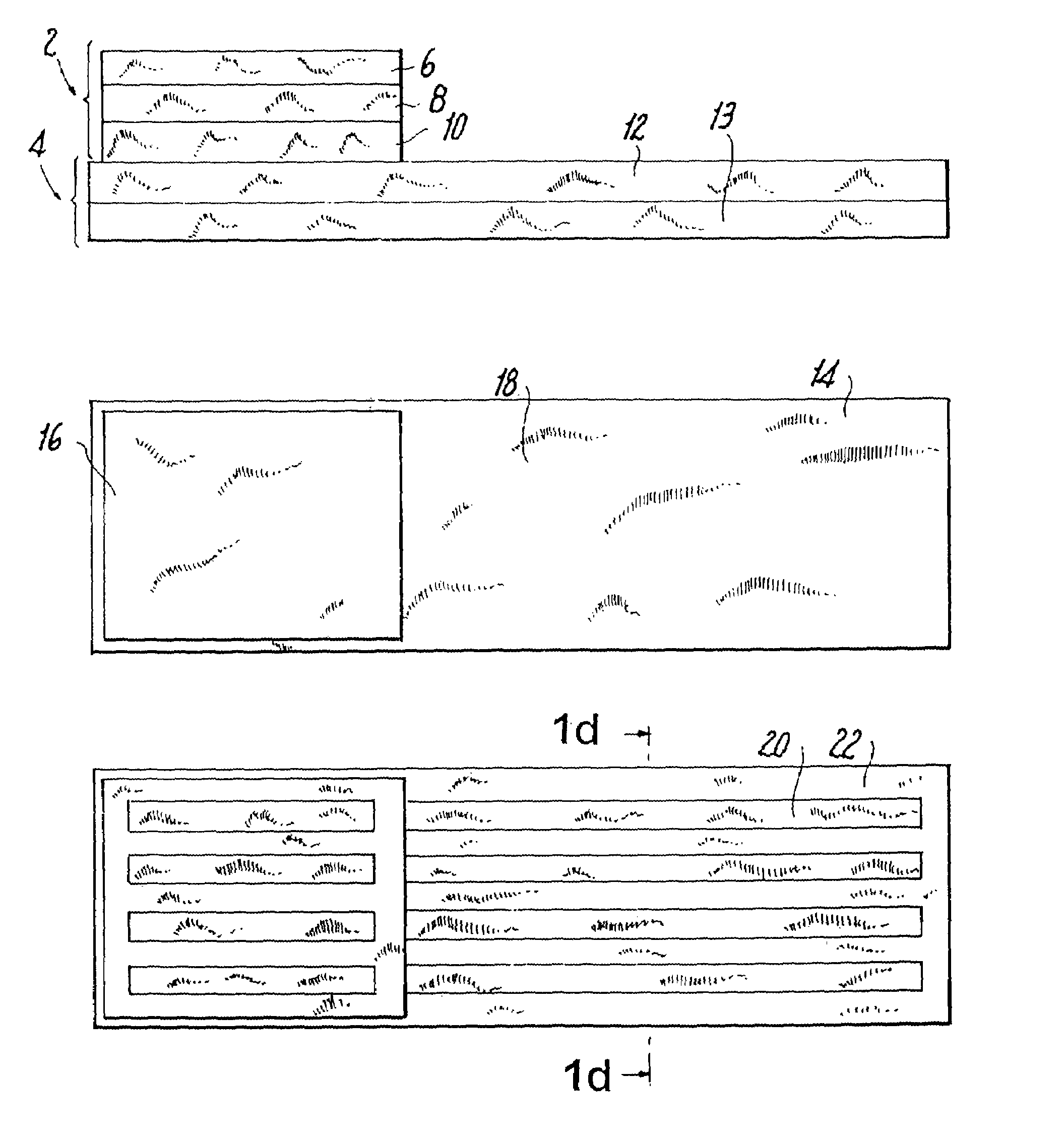
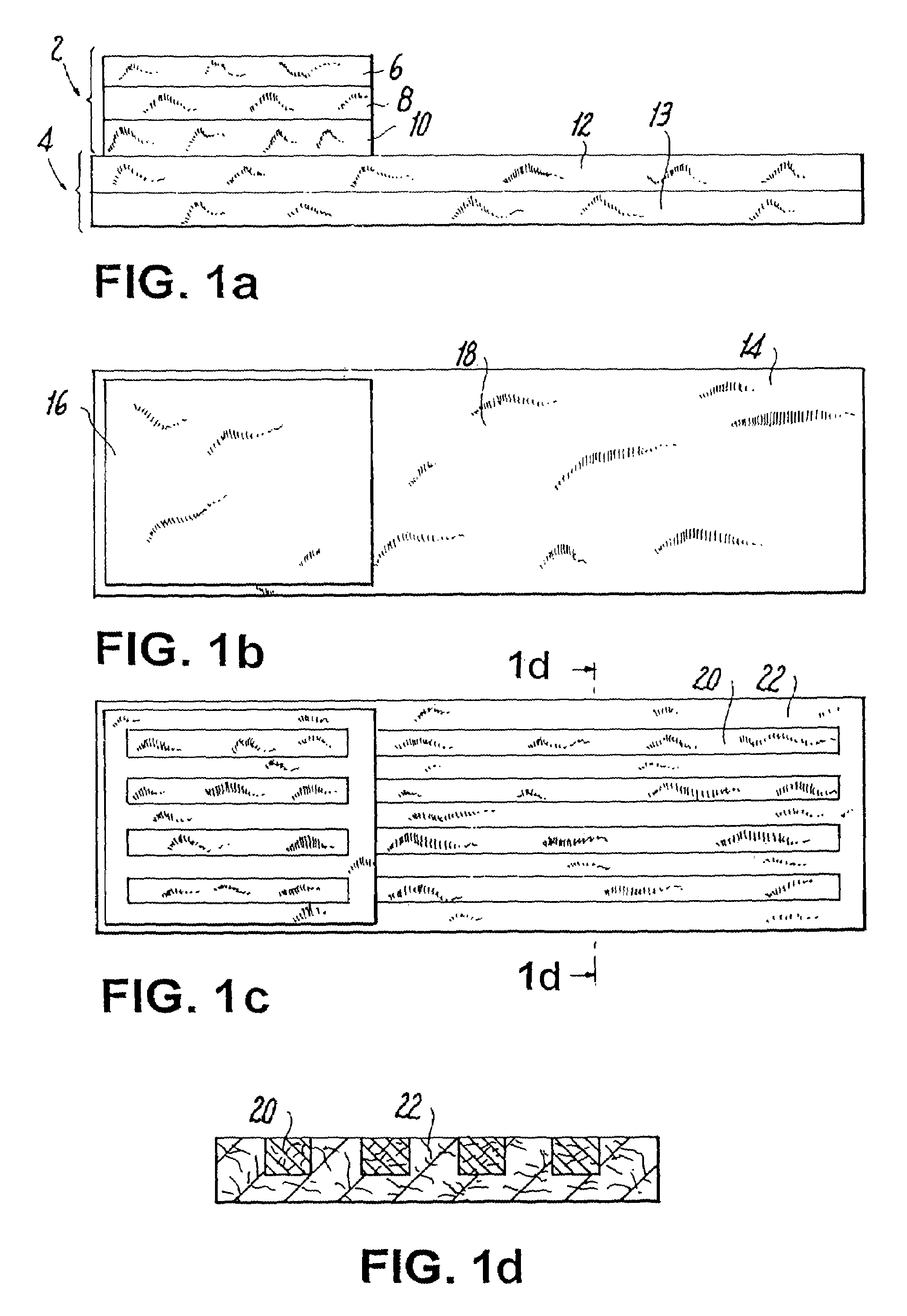
[0080]An absorbent structure was assembled by joining together upper ply (component A1) and lower ply (component B1) described below. Both absorbent components were made by dry forming (or airlaying) on an M&J pilot machine. The mechanical and absorbency properties of the structure are depicted in Tables 1, 3 and 4. The structure exhibited improved performance compared to the performance found with commercial structures as described herein, due to the combination of profiled absorbency and appropriate levels of conformability and integrity.

[0081]Component A1. Two forming heads were used and they were fed with the same composition and amount of raw materials. The product was laid on a carrier of 40 gsm Brand 6810 polyester (polyethylene terephthalate) nonwoven (PGI). This material constituted the top stratum of the upper ply. The basis weights and compositions of the middle stratum and of the bottom stratum were the same, the basis weight being 160 gsm and the composition being 56.3%...

example 2

[0084]An absorbent structure was assembled by joining together Components A2 and B2 described below. Both absorbent components were made by dry forming on an M&J pilot machine. In the resultant structure component A2 is the upper ply and component B2 is the lower ply. The mechanical and absorbency properties of the structure are depicted in Tables 1, 3 and 4. The structure exhibited improved performance due to the combination of profiled absorbency and appropriate levels of conformability and integrity.

[0085]Component A2. The middle stratum of the Upper Ply was formed by feeding the first forming head with HPF fluff (Buckeye Technologies, Memphis, Tenn.) at 40 gsm and 2.8 dpf T-255 binder fiber (Kosa, Salisbury, N.C.) at 2.5 gsm. The second head was used to form the top stratum of the upper ply. The second forming head was fed with HPF fluff (Buckeye Technologies, Memphis, Tenn.) at 100 gsm, Z1049 SAP (Stockhausen, Greensboro, N.C.) at 94 gsm, and 2.8 dpf T-255 binder fiber (Kosa, S...

example 3

[0087]An absorbent structure was assembled by joining together Components A3 and B3 described below. Both absorbent components were made by dry forming on a DanWeb pilot machine. In the resultant structure Component A3 is the upper ply and Component B3 is the lower ply. The mechanical and absorbency properties of the structure are depicted in Tables 1, 3 and 4. The structure exhibited improved performance due to the combination of profiled absorbency and appropriate levels of conformability and integrity.

[0088]Component A3. The first forming head was fed with Foley Fluff (Buckeye Technologies, Memphis, Tenn.) at 60 gsm and 2.8 dpf T-255 binder fiber (Kosa, Salisbury, N.C.) at 10 gsm, to form the bottom stratum of the upper ply. The second head was used to form the middle stratum of the upper ply. The second head was fed with Foley Fluff at 98 gsm, SXM70 SAP (Stockhausen, Greensboro, N.C.) at 62.5 gsm, and 2.8 dpf T-225 binder fiber (Kosa, Salisbury, N.C.) at 19.5 gsm. The third head...


PUM

PropertyMeasurementUnit
lengthaaaaaaaaaa
densityaaaaaaaaaa
lengthaaaaaaaaaa

Abstract

Disclosed is an absorbent structure having wet integrity greater than about 4.0 mN/gsm, softness greater than 8.0/J, pliability greater than about 70/N, and providing a substantially dry liquid-accepting surface after receiving a quantity of liquid. The structure includes an upper ply having an upper fluid receiving surface and a lower surface and including (i) a top stratum including synthetic matrix fibers bonded with a binder, the matrix fibers having length from about 2 to about 15 mm; (ii) a middle stratum in fluid communication with the top stratum, the middle stratum including natural fibers, superabsorbent particles and a binder; and (iii) a bottom stratum in fluid communication with the middle stratum, the bottom stratum including natural fibers and a binder. The structure also includes a lower ply in fluid communication with the upper ply, the lower ply having an upper surface and a lower surface and including at least one stratum including natural fibers, superabsorbent polymer particles, and a binder, wherein the lower surface of the upper ply has a surface area less than about 80% of the upper surface area of the lower ply.

Description

[0001]This is a continuation of application Ser. No. 09 / 475,850, filed Dec. 30, 1999 now U.S. Pat. No. 6,562,742. Also attached as an appendix to the specification is U.S. Patent Publication No. 2003 / 0012919 A1, the published parent application. Each of these prior applications is hereby incorporated herein by reference, in its entirety.CROSS-REFERENCE TO RELATED APPLICATIONS[0002]This application claims priority under 35 U.S.C. § 119, based on U.S. Provisional Application Ser. No. 60 / 116,036, filed Jan. 11, 1999, the entire disclosure of which is hereby incorporated by reference.[0003]1. Field of the Invention[0004]The present invention relates to high-capacity, thin and highly conformable absorbent structures, useful in absorbent articles including baby diapers, adult incontinence products, sanitary napkins and the like. More particularly, the present invention relates to absorbent structures containing matrix fibers, binders and superabsorbent polymers, the structure having an x-...

Claims


Application Information

Patent Timeline
Patent Type & Authority Patents(United States)
IPC IPC(8): B23B5/18B23B5/24A61F13/53A61F5/44A61F13/15A61F13/49A61F13/534B32B5/26B32B27/04D04H1/40D04H1/58
CPCA61F13/535B32B5/26B32B27/02D04H13/002D04H13/003B32B27/04Y10T428/239Y10T442/659Y10T442/673Y10T442/60Y10T442/653Y10T442/30B32B27/00
Inventor DUTKIEWICZ, JACEK K.WAHAL, SANJAYHOOD, RYAN K.ERSPAMER, JOHN P.BOEHMER, BRIAN E.
Owner BUCKEYE TECH INC
Why Eureka
Try Eureka