Hybrid stent and method of making

a technology of endoprosthesis and hybrid stent, which is applied in the direction of prosthesis, pipes, medical preparations, etc., can solve the problems of chromium oxide layer present on the surface of stainless steel stents to prevent corrosion, chromium oxide layer may have a tendency to degrade during long-term use within the body, and alloys can sometimes be excessively radiopaque or lack of sufficient strength, etc., to achieve the effect of improving visibility

Inactive Publication Date: 2010-04-06
ABBOTT CARDIOVASCULAR
View PDF64 Cites 94 Cited by
  • Summary
  • Abstract
  • Description
  • Claims
  • Application Information

AI Technical Summary

Benefits of technology

[0019]The present invention is directed to a stent that overcomes the shortcomings of previously known devices by embodying a polymeric material combined with a metallic material to improve visibility under MRI, computer tomography and fluoroscopy.
[0020]In one embodiment of the stent of the present invention, metallic rings are positioned between an outer layer of a first polymeric material and an inner layer of a second polymeric material. In other words, the metallic rings are sandwiched in between the first and second polymeric materials. The rings are connected by links which are formed by the first and second polymeric materials. The metallic rings generally are visible under fluoroscopy while the polymeric material provides good visibility using MRI.
[0023]In another embodiment, in order to provide higher visibility under fluoroscopy, the polymeric materials are compounded with an appropriate radiopacifier such as the powder of barium sulfate, bismuth subcarbonate, bismuth trioxide, bismuth oxychloride, tungsten, tantalum, iridium, gold, or other dense metal. To define a biodegradable structure, the polymeric materials are compounded with a biodegradable radiopacifier that renders it visible under fluoroscopy and can be safely released in the body. Such radiopacifiers include particles of an iodinated contrast agent and bismuth salts.
[0025]Each embodiment of the present invention also can include a therapeutic drug or therapeutic agent associated with the first and second polymeric materials. For example, one or more therapeutic drugs can be loaded into either or both of the first and second polymeric materials to prevent or reduce the likelihood of restenosis or to otherwise treat the vessel or artery.

Problems solved by technology

Although both materials are generally regarded as being bio-compatible, some recent concerns have arisen regarding the long term biocompatibility of stainless steel.
In addition, the chromium oxide layer present on the surface of stainless steel stents to prevent corrosion may have a tendency to degrade during long term use within the body.
However, these alloys can sometimes either be excessively radiopaque or may lack sufficient strength for recoil, radial strength requirements, and long-term use in a dynamic vascular setting.
This tends to overwhelm the image of the tissue surrounding the stent and obscures visualization of the stent lumen.
Due to the lack of an appropriately radiopaque material, simply constructing a stent wholly out of a single material has heretofore not resulted in a stent with the optimal combination of mechanical properties and radiopacity.
Conventional radiopaque markers, however, have a number of limitations.
Additionally, galvanic corrosion may result from the contact of two disparate metals, i.e., the metal used in the construction of the stent and the radiopaque metal of the marker.
Such corrosion could eventually cause the marker to separate from the stent which may be problematic should the marker be swept downstream within a vessel.
However, a number of disadvantages are associated with this approach as well.
When the stent is expanded certain portions undergo substantial deformation, creating a risk that cracks may form in the plating or coating causing portions of the plating to separate from the underlying substrate.
This has the potential for creating jagged edges that may inflict physical trauma on the lumen wall tissue or cause turbulence in the blood flowing past the stent, thereby inducing thrombogenesis.
Moreover, once the underlying structural material becomes exposed to an electrolytic solution such as blood, interfaces between the two disparate metals become subject to galvanic corrosion.
Over time, galvanic corrosion may also lead to separation of the plated material from the underlying substrate.
However, in addition to the potential disadvantages stated above, other drawbacks may exist.
Exposure to ionizing radiation and nephrotoxic iodinated contrast agents are intrinisic to the technique, as well as the need to wear leaded personal protective equipment.
In patients undergoing MRI, there are numerous devices which are poorly seen, if they are visible at all, on the MR image artifact.
Due to their small size, current metal stents are sometimes difficult to see in fluoroscopy as they attenuate the x-ray beam very little.
In MRI, the problem is that ferromagnetic and metallic based stents are difficult to see as they can create a large imaging artifact (a region of signal void or diminishment, which can extend beyond the stent boundaries).
Unfortunately, this creates a situation analogous to fluoroscopy with a stent that is difficult to visualize.
However, unlike x-ray computer tomography, MRI does not use ionizing radiation.
This presently is not an easily implemented solution for small, free-standing devices such as stents.
Because stents are constructed of electrically conductive materials, they suffer from a Faraday Cage effect when used with MRI's.
Furthermore, the stent Faraday Cage likely impedes the escape of whatever signal is generated in the lumen.
The stent's high magnetic susceptibility, however, perturbs the magnetic field in the vicinity of the implant.
This alters the resonance condition of protons in the vicinity, thus leading to intravoxel dephasing with an attendant loss of signal.
The net result with current metallic stents, most of which are stainless steel, is a signal void in the MRI images.
Other metallic stents, such as those made from Nitinol, also having considerable signal loss in the stent lumen due to a combination of Faraday Cage and magnetic susceptibility effects.
Unfortunately, most metal stents, particularly of stainless steel, obliterate MRI images of the anatomy in their vicinity and obscure the stent lumen in the image.
This solution is limited by the need for stents to have adequate radial strength and scaffolding.
Being new to the cardiology and interventional fields, and being an expensive technology, MRI utilization and implementation will vary by medical specialty, medical institution, and even on a country by country basis.
However, MRI has the potential to supplant, and potentially substitute for fluoroscopy in the future.

Method used


Image

  • Hybrid stent and method of making
  • Hybrid stent and method of making
  • Hybrid stent and method of making

Examples


Embodiment Construction

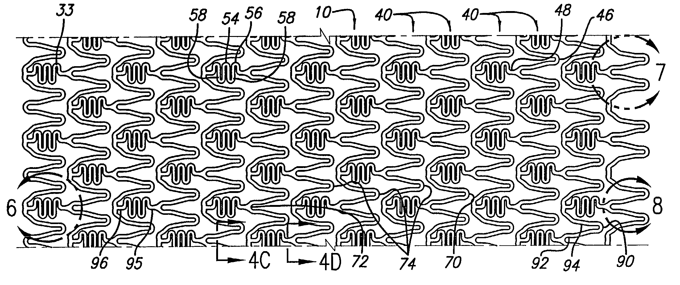
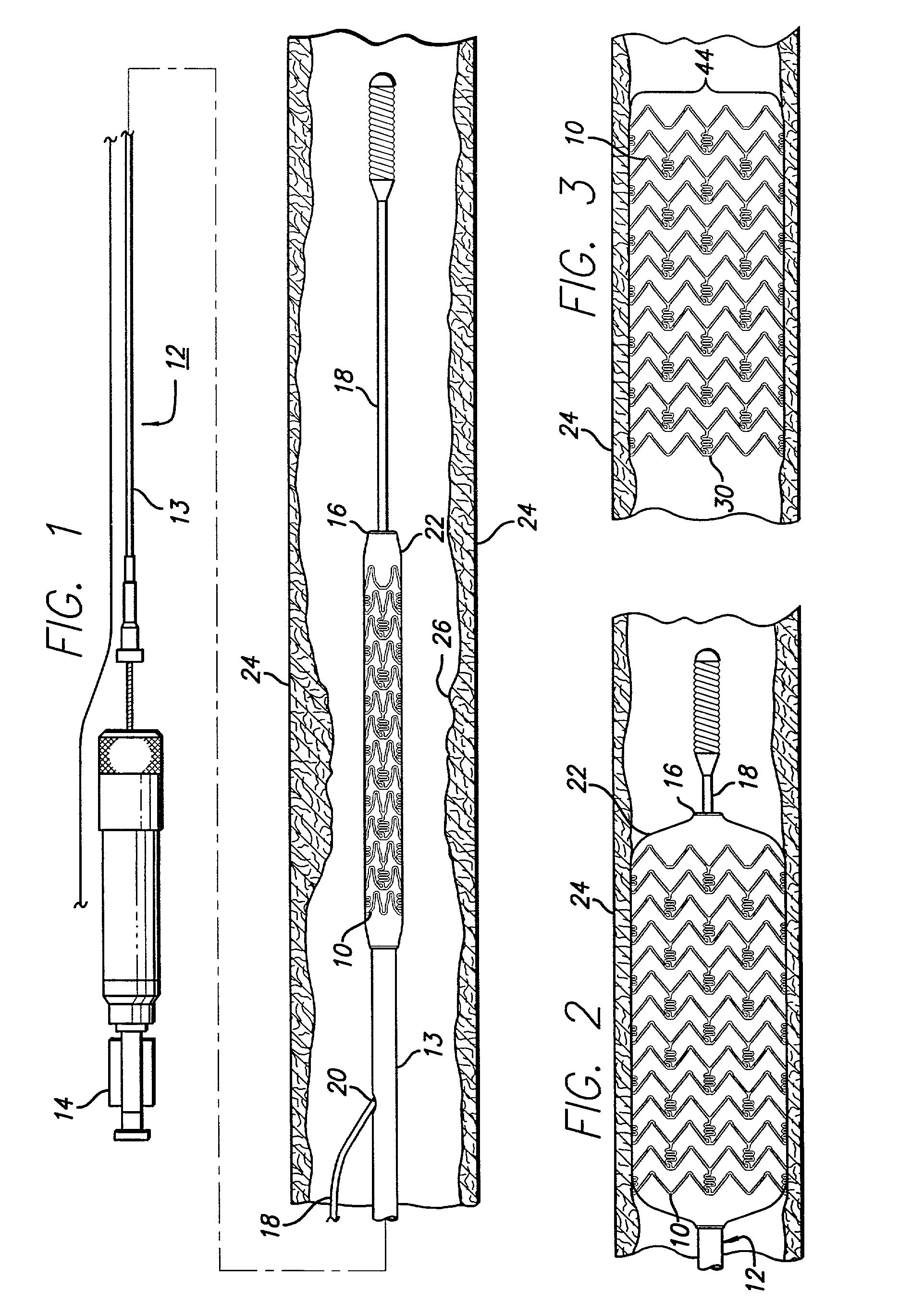
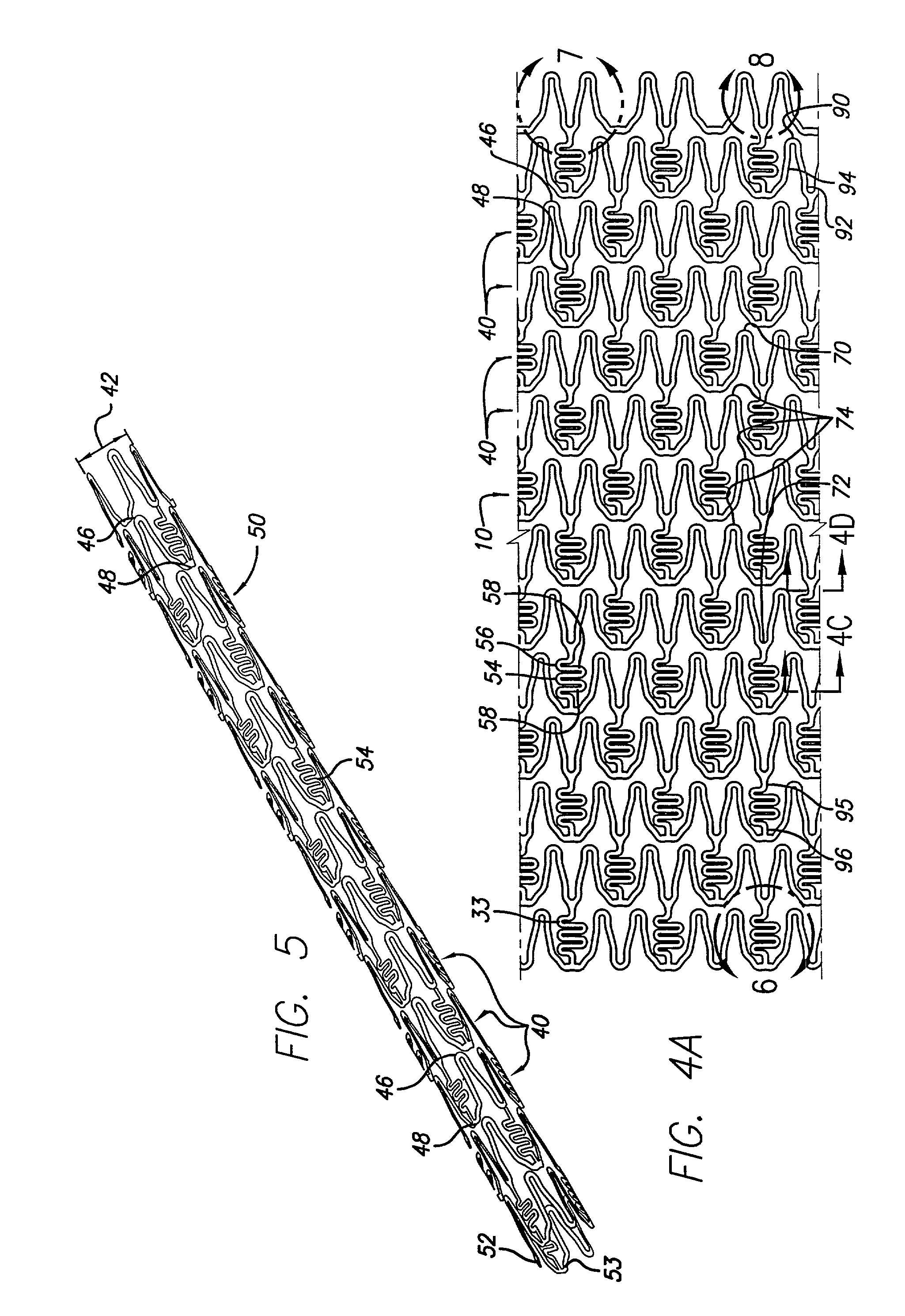
[0047]The hybrid stent of the present invention combines the features and advantages of metallic stents with those of polymeric stents so that the combined hybrid stent provides the required structural support for a vessel such as a coronary artery, yet is visible under any of MRI, computer tomography or x-ray fluoroscopy. In general, metallic rings are aligned along a stent longitudinal axis and an outer layer of a first polymeric material covers the outer surface of the metallic rings, and an inner layer of a second polymeric material covers the inner surface of the metallic rings. At least one link connects adjacent metallic rings whereby the links are formed by the inner and outer polymeric materials. Virtually any stent pattern, of the many known stent patterns, can be used to form the hybrid stent of the present invention. Thus, while certain embodiments of the hybrid stent are described herein, they are for exemplary purposes only, and are not meant to be limiting.

[0048]Turni...


PUM

PropertyMeasurementUnit
thicknessaaaaaaaaaa
wall thicknessaaaaaaaaaa
temperaturesaaaaaaaaaa

Abstract

A stent is formed by encasing or encapsulating metallic rings in an inner polymeric layer and an outer polymeric layer. At least one polymer link connects adjacent metallic rings. The stent is drug loaded with one or more therapeutic agent or drug, for example, to reduce the likelihood of the development of restenosis in the coronary arteries. The inner and outer polymeric materials can be of the same polymer or different polymer to achieve different results, such as enhancing flexibility and providing a stent that is visible under MRI, computer tomography and x-ray fluoroscopy.

Description

BACKGROUND OF THE INVENTION[0001]This invention relates to endoprosthesis devices, generally called stents, and more particularly, to achieving desired visibility of such devices under magnetic resonance imaging (MRI), computer tomography, and fluoroscopy.[0002]Stents are generally thin walled tubular-shaped devices composed of complex patterns of interconnecting struts which function to hold open a segment of a blood vessel or other body lumen such as a coronary artery. They also are suitable for supporting a dissected arterial lining or intimal flap that can occlude a vessel lumen. At present, there are numerous commercial stents being marketed throughout the world. These devices are typically implanted by use of a catheter which is inserted at an easily accessible location and then advanced through the vasculature to the deployment site. The stent is initially maintained in a radially compressed or collapsed state to enable it to be maneuvered through the lumen. Once in position,...

Claims


Application Information

Patent Timeline
Patent Type & Authority Patents(United States)
IPC IPC(8): B29C47/00A61F2/06F16L11/04A61F2/82
CPCA61F2/82A61F2/91A61F2/915A61L31/022A61L31/10A61L31/18B29C41/08B29C41/14B29C41/20B29C41/22B23K26/4065B23K26/38B29C65/16B29C65/68Y10T29/49906A61F2002/072A61F2002/91558A61F2250/0032A61F2250/0063A61F2250/0067B29L2031/7534A61F2/07A61F2230/0013A61F2230/0054Y10T428/139Y10T428/1393A61F2/852B23K2103/50B23K2103/42B23K2103/54A61F2210/0076A61F2230/0069A61F2240/001A61K31/727B23K26/402A61F2/04A61F2/89A61L31/16A61L31/048A61L2300/236A61L2300/606B29K2027/18
Inventor PRABHU, SANTOSH
Owner ABBOTT CARDIOVASCULAR
Why Eureka
Try Eureka