Heat spreader, heat sink, heat exchanger and PDP chassis base

a heat spreader and chassis base technology, applied in the direction of indirect heat exchangers, electrical apparatus construction details, lighting and heating apparatus, etc., can solve the problems of low conversion efficiency, user discomfort and inconvenience, and the power of 350 w 450 w gives out the most power, so as to reduce the installation space, reduce the heat spread resistance, and spread the heat generated locally

Active Publication Date: 2007-02-13
KOREA INST OF SCI & TECH
View PDF9 Cites 53 Cited by
  • Summary
  • Abstract
  • Description
  • Claims
  • Application Information

AI Technical Summary

Benefits of technology

[0007]In addition, a heat sink is used to emit heat generated in a CPU of an electronic device and in an electronic communication component such as a signal-amplifying module of a mobile communication repeater. In this case, when heat is generated locally in a highly integrated electronic component, the heat can not be spread effectively to a cooling fin of the heat sink through a heat spreader of the heat sink. In order to improve heat spread performance, in a conventional art, a method of decreasing heat spread resistance by thickening a thickness of a heat spreader of a heat sink made of aluminum or copper is used. But this method has disadvantageous effects that the heat sink cannot be installed in a small space due to an excessive increased weight and volume.
[0008]In order to solve such a problem, an invention (hereinafter, referred to as ‘known invention 1’) reducing an installation space by forming a depressed portion 14, 17 is disclosed in Korean Patent Publication Laid-Open No. 2002-0083712. However, the invention 1 has still defects that a thickness of heat sink should be thickened in order to decrease heat spread resistance.
[0009]In addition, as another method to spread heat generated locally, a heat spreader including a plate-shaped heat pipe to using a principle of a classical heat pipe is disclosed in Korean Patent Publication Laid-Open No. 2003-0042652. Such a type of heat spreader can be made a thin film structure, thereby having a small size and a lightweight and also having excellent heat spread performance. But the type of heat spreader is applied to very-limited area due to occurring a significant deterioration in performance since an internal space between two thin films has to be maintained in a vacuum, heat spread performance is deteriorated by a change of a degree of vacuum in the internal space after the heat spreader is used for a long time, and if the heat pipe is installed in such a manner that its longitudinal direction is vertical to a gravity direction, the performance of the heat pipe becomes deteriorated because it is difficult for a refrigerant to return against gravity in view of characteristics of the heat pipe.SUMMARY OF THE INVENTION
[0010]Therefore, an object of the present invention is to provide a heat spreader capable of reducing its weight and size and accelerating heat spread without a performance change regardless of an installation direction since the performance of heat transfer is improved and thus its thickness is formed thin.
[0011]To achieve these and other advantages and in accordance with the purpose of the present invention, as embodied and broadly described herein, there is provided heat spreader including thin films opposite to each other; cooling liquid filling an internal space between thin films; and a vibration generating means for vibrating the liquid.

Problems solved by technology

However, a 42 inch PDP TV consuming about 350 W˜450 W power gives out most power as heat because of low converting efficiency from electric energy to light energy.
Accordingly, temperature on front surface of the PDP is getting higher and higher to be about 50° C. by the heat of 150 W transferred to the front surface of the PDP, thereby causing users to feel unpleasantness and inconvenience.
In spite of this effort, when heat distribution in the surface thereof is not uniform, and when a white image combined with 3 primary colors is locally displayed for a long time, excessive heat is concentrated locally therein, and thus an afterimage of the white image is displayed for minutes even after the white image has been removed, thereby causing a degradation in image quality.
In this case, when heat is generated locally in a highly integrated electronic component, the heat can not be spread effectively to a cooling fin of the heat sink through a heat spreader of the heat sink.
But this method has disadvantageous effects that the heat sink cannot be installed in a small space due to an excessive increased weight and volume.
But the type of heat spreader is applied to very-limited area due to occurring a significant deterioration in performance since an internal space between two thin films has to be maintained in a vacuum, heat spread performance is deteriorated by a change of a degree of vacuum in the internal space after the heat spreader is used for a long time, and if the heat pipe is installed in such a manner that its longitudinal direction is vertical to a gravity direction, the performance of the heat pipe becomes deteriorated because it is difficult for a refrigerant to return against gravity in view of characteristics of the heat pipe.

Method used


Image

  • Heat spreader, heat sink, heat exchanger and PDP chassis base
  • Heat spreader, heat sink, heat exchanger and PDP chassis base
  • Heat spreader, heat sink, heat exchanger and PDP chassis base

Examples


Embodiment Construction

[0025]Reference will now be made in detail to the preferred embodiments of the present invention, examples of which are illustrated in the accompanying drawings.

[0026]Only, well-known function and structure are not described in detail so as not to obscure the present invention

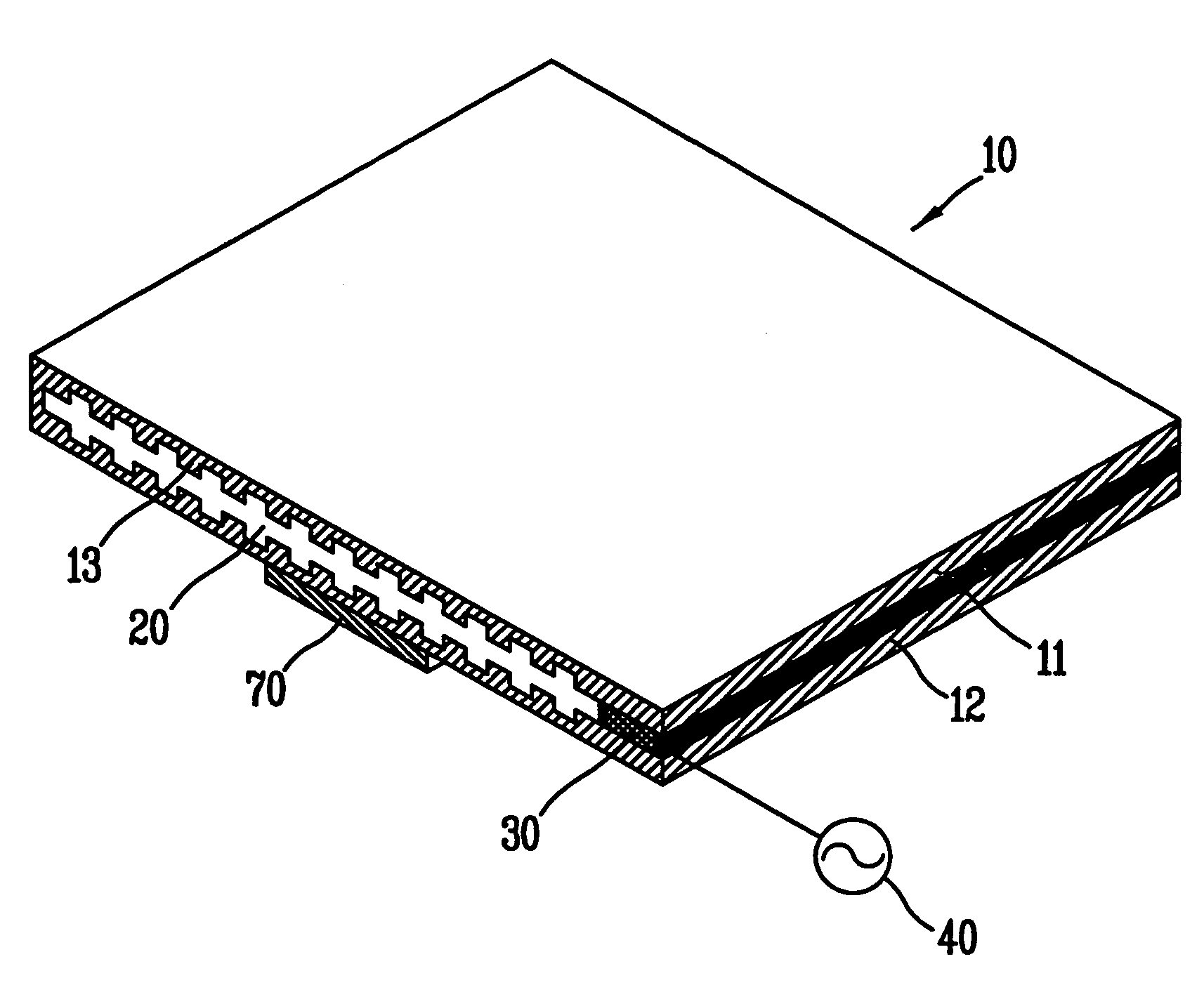
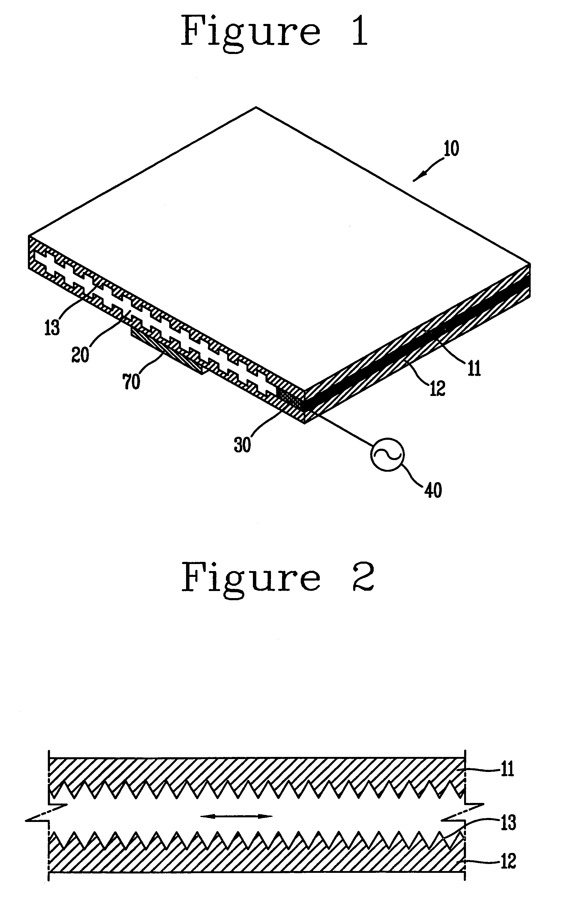
[0027]FIGS. 1 and 2 are views showing a structure of a heat spreader in accordance with one embodiment of the present invention, wherein FIG. 1 is a cut perspective view of a heat spreader and FIG. 2 is a cross sectional view showing a modified example of a concavo-convex form of FIG. 1.

[0028]As shown therein, a heat spreader 10 in accordance with one embodiment of the present invention includes thin films 11, 12 opposite to each other and forming an internal space 20 therebetween; cooling liquid filling the internal space 20 and a vibration generating means for vibrating the cooling liquid.

[0029]The thin films 11, 12 are made of metal having high thermal conductivity, preferably, such as aluminum, copper or th...


PUM


Abstract

A heat spreader includes thin films opposite to each other; cooling liquid filling an internal space between the thin films; and a vibration generating means for vibrating the liquid. Accordingly, the heat spreader has excellent heat spread performance compared to a conventional heat spreader, so can have an ultra slim type structure. Also, the heat spreader has excellent heat spread performance regardless of a direction of gravity, and a space between the thin films is sealed in a state of an atmospheric pressure, to maintain the improved heat spread performance for a long time.

Description

BACKGROUND OF THE INVENTION[0001]1. Field of the Invention[0002]The present invention relates to a heat spreader, more specifically, to a heat spreader having a structure of improved heat transfer rate and thus enabling reliable heat spread characteristics regardless of its installation direction as well as of a light weight and small size.[0003]2. Description of the Background Art[0004]Recently, a Plasma Display Panel (hereinafter, referred to as “PDP”) TV which leads a large screen display market worldwide has a large screen and also an ultra slim type structure so that the PDP TV needs a small space for installation can be easily mounted on a wall. However, a 42 inch PDP TV consuming about 350 W˜450 W power gives out most power as heat because of low converting efficiency from electric energy to light energy. Out of totally emitted heat, about 250 W heat is emitted from double glass plate of the PDP and about 100 W heat is emitted from an image signal unit and a power unit arrang...

Claims


Application Information

Patent Timeline
Patent Type & Authority Patents(United States)
IPC IPC(8): H01L23/34H05K7/20F28D15/02H01J17/28H01L23/36H01L23/367H01L23/473
CPCH01L23/367H01L23/473H05K7/2099H01L2924/0002H01L2924/00H01J17/28
Inventor KIM, SEO YOUNG
Owner KOREA INST OF SCI & TECH
Why Eureka
Try Eureka