Sensor structure and magnetic field sensor

a sensor and magnetic field technology, applied in the direction of magnetic field magnitude/direction, measurement devices, instruments, etc., can solve the problems of reducing the field operating range with respect to the range, affecting the performance of the device directly, and m is precisely the order of magnitude of positioning, so as to improve the reproducibility of sensor performance and the effect of greater sensitivity

Inactive Publication Date: 2007-02-13
COMMISSARIAT A LENERGIE ATOMIQUE ET AUX ENERGIES ALTERNATIVES
View PDF4 Cites 21 Cited by
  • Summary
  • Abstract
  • Description
  • Claims
  • Application Information

AI Technical Summary

Benefits of technology

[0008]With reference to the state of the related art described above, the invention proposes a sensor with a structure which makes it possible to measure weak fields, for example below 50 Oersteds, which offers improved reproducibility in terms of sensor performances.

Problems solved by technology

A second drawback of the prior art described above stems from the fact that, in the configuration described in the article, the positioning of the GMRs with respect to the edges of the magnets is very critical and influences the performances of the device directly.
This decrease is a major drawback in GMR operation, since it reduces the field operating range with respect to the range that it was thought could be measured.
In addition, it turns out that 1 μm is precisely the order of magnitude of the positioning error obtained with standard photolithography machines used in microelectronics.
It should also be noted that the same positioning error degrades the plate to plate reproducibility of plates from the same batch.

Method used


Image

  • Sensor structure and magnetic field sensor
  • Sensor structure and magnetic field sensor
  • Sensor structure and magnetic field sensor

Examples


Embodiment Construction

OF EMBODIMENTS

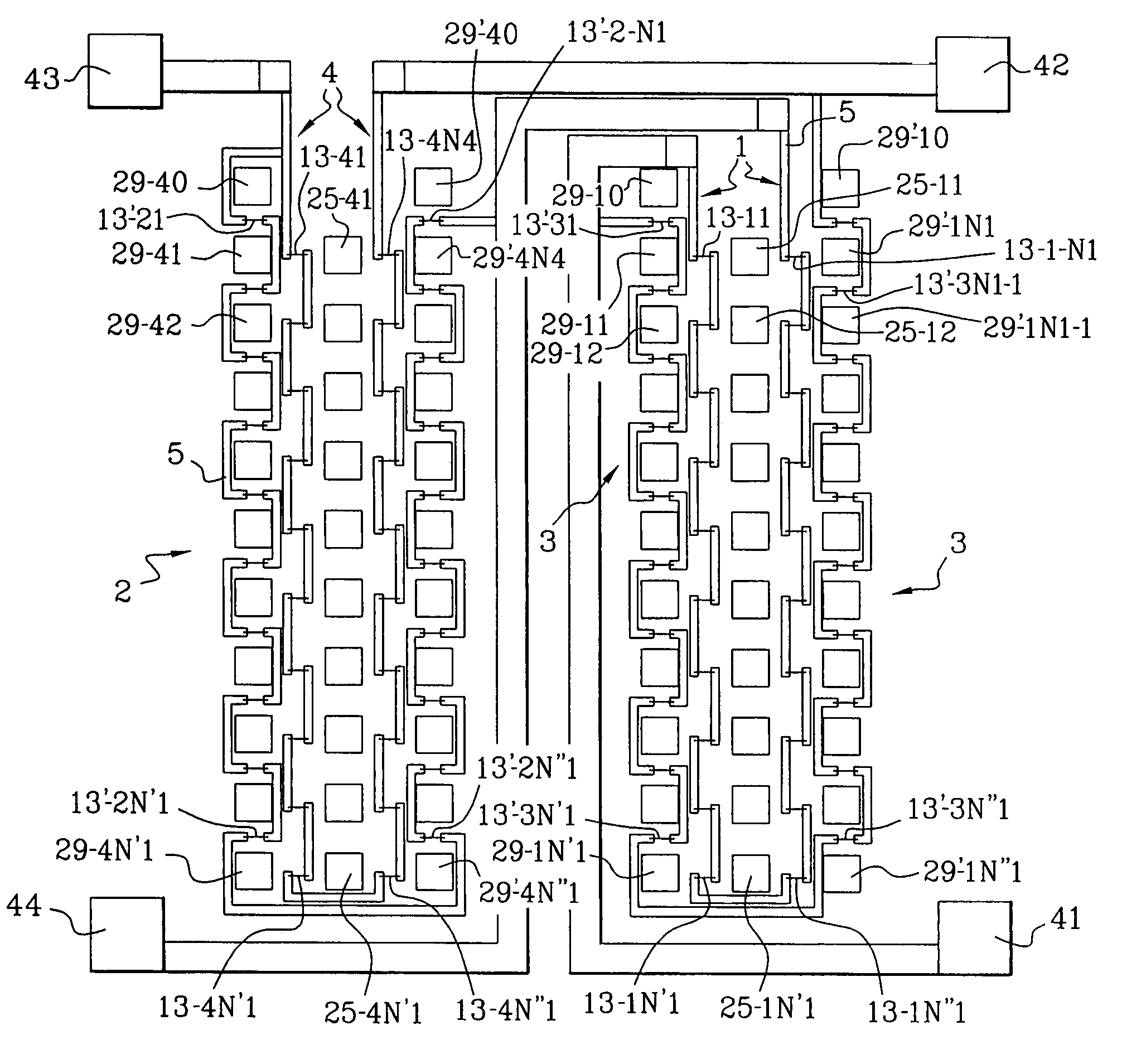
[0024]In the figures, the components having the same function are represented by identical reference numbers. The term rectangular which will be used frequently to characterise the shape of the magnets or magnetoresistors must be taken in the most general sense of the term which includes square shapes.

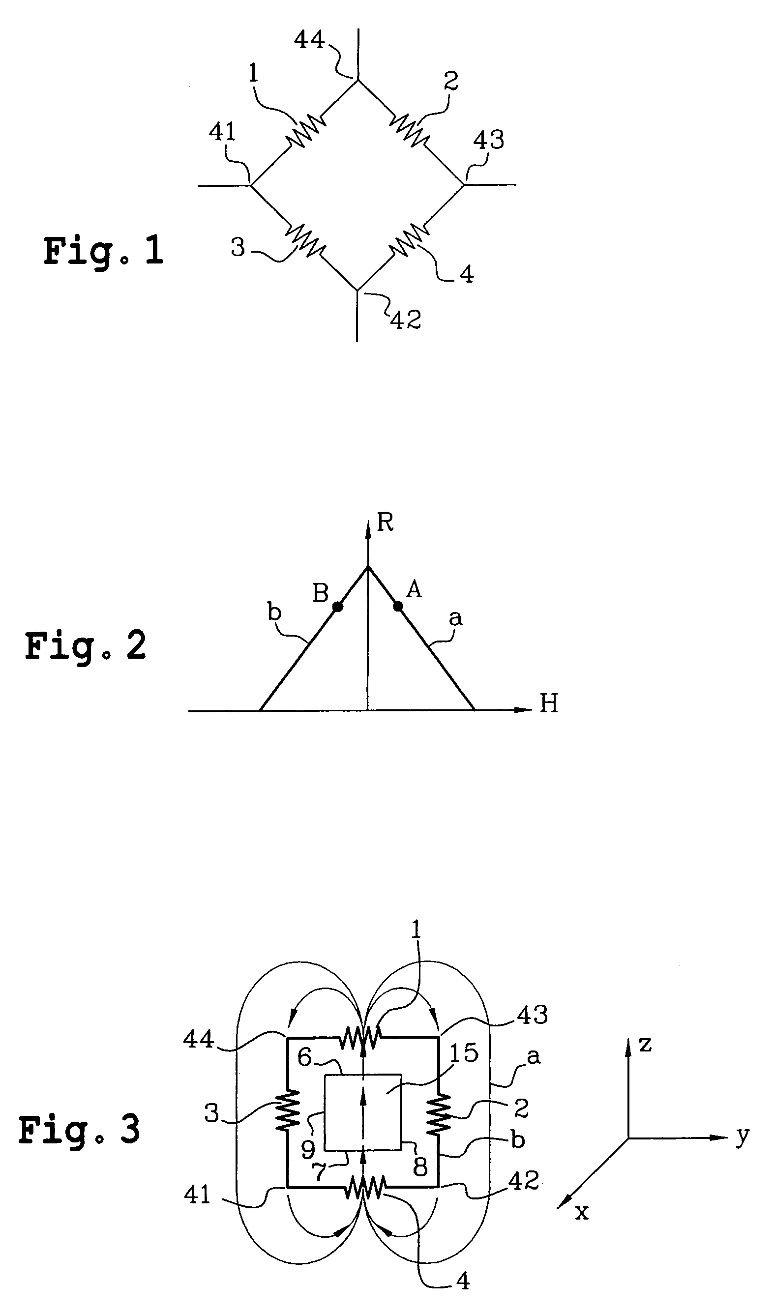
[0025]The operation of a dividing bridge and the operation of a Wheatstone bridge should first of all be pointed out with reference to FIG. 1.

[0026]A dividing bridge is formed as described above by two magnetoresistors for example magnetoresistors 1 and 3 connected in series between a point 44 and a point 42. A reference voltage is applied between the points 42, 44. The magnetoresistors 1 and 3 are polarised by magnetic fields of opposite directions. An output voltage measured at the terminals of either of the two magnetoresistors 1, 3 is representative of the variation of the value of the magnetoresistors. This magnetoresistor value is itself a function of the value of t...


PUM


Abstract

A method and an apparatus of a magnetic field sensor structure are disclosed. The magnetic field sensor structure is formed by a bridge of four magnetoresistors (1–4), wherein each magnetoresistor has a longitudinal direction, and each magnetoresistor (1–4) is polarised by magnets (15–19). Also, each magnet has a main magnetisation field along an axial magnetisation direction, and a magnetic leakage field. The polarisation magnets (15–19) and the magnetoresistors (1–4) are arranged in the form of layers on the same substrate. In one embodiment, the polarisation magnets (15–19) are at the same level as the magnetoresistors (1–4) wherein the polarisation magnets (15–19) have the same main magnetisation direction, which is contained in the plane of the layers. The magnetoresistors have their longitudinal direction parallel with that of the axial direction of the magnets. In one embodiment, two magnetoresistors are arranged in the axial field of magnets and two others are in the magnet leakage field.

Description

FIELD OF THE INVENTION[0001]The invention relates to the field of structures for sensors and sensors incorporating such structures, intended to measure magnetic fields created for example by electric currents, magnets, any material or magnetic object or the terrestrial magnetic field or any other magnetic field.STATE OF THE RELATED ART[0002]The article referenced [1] in an appendix to the present disclosure discloses a method to polarise 4 giant magnetoresistors (GMR) of a Wheatstone bridge in a paired opposing fashion using integrated magnet leakage fields. According to the prior art, not described in this article, the Wheatstone bridge comprises 4 GMRs connected in series in a loop. This gives four connection points between two consecutive GMRs of the series. Two pairs of non-consecutive connection points define two diagonals of the bridge, a first and a second. A voltage is applied along the first diagonal. When the bridge is in equilibrium, a voltage measured along the second di...

Claims


Application Information

Patent Timeline
Patent Type & Authority Patents(United States)
IPC IPC(8): G01R33/02H01L43/00G01R33/09
CPCG01R33/09
Inventor BARAGATTI, CLAIRECUCHET, ROBERTVIEUX-ROCHAZ, LINE
Owner COMMISSARIAT A LENERGIE ATOMIQUE ET AUX ENERGIES ALTERNATIVES
Why Eureka
Try Eureka