
Computer

a computer and computer technology, applied in the computer field, can solve the problems of large noise generated during the operation of the computer system, deterioration of the performance of the internal parts, and inability to function at all, and achieve the effect of efficient cooling system and effective cooling of the installed heat generating components

Inactive Publication Date: 2007-02-13
ZALMAN TECH CO LTD
View PDF17 Cites 52 Cited by
  • Summary
  • Abstract
  • Description
  • Claims
  • Application Information

AI Technical Summary

Benefits of technology

[0009]The present invention provides a computer with an efficient cooling system that can effectively cool heat generating components installed in a computer case without generating noise.

Problems solved by technology

When the temperatures of the internal parts are elevated by heat generated by these heat generating elements, the performances of the internal parts deteriorate and they may not function at all in the worst case.
This is one of the critical issues that the computer industry is facing.
However, such conventional computer cooling systems have the following problems.
Since a plurality of cooling fans, which turn at a high speed, are installed to cool the heat generating sources in the computer case, a large amount of noise is generated during operation of the computer system.
Such noise generated by the cooling fans generally bothers computer users and lowers working efficiency.
Another problem is that external dust particles stick to the parts in the computer case as the air is continuously exchanged with a large amount of external air by the cooling fan during the operation of the computer system.
This problem becomes worst due to the electrostatic force generated by the internal parts and finally may lead to operational failures of the parts.
Another problem with the conventional computer cooling system lies in the inefficiency due to the active cooling of the heat generating components within the computer case.
Thus, the heat generating components cannot be effectively cooled using the warm air in the computer case.

Method used


Image

  • Computer
  • Computer
  • Computer

Examples


first embodiment

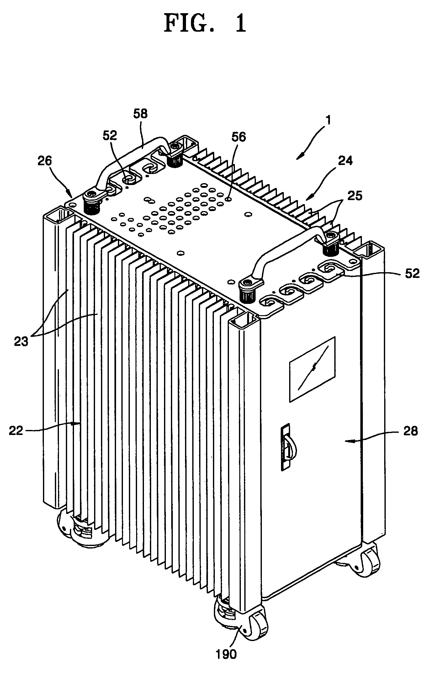
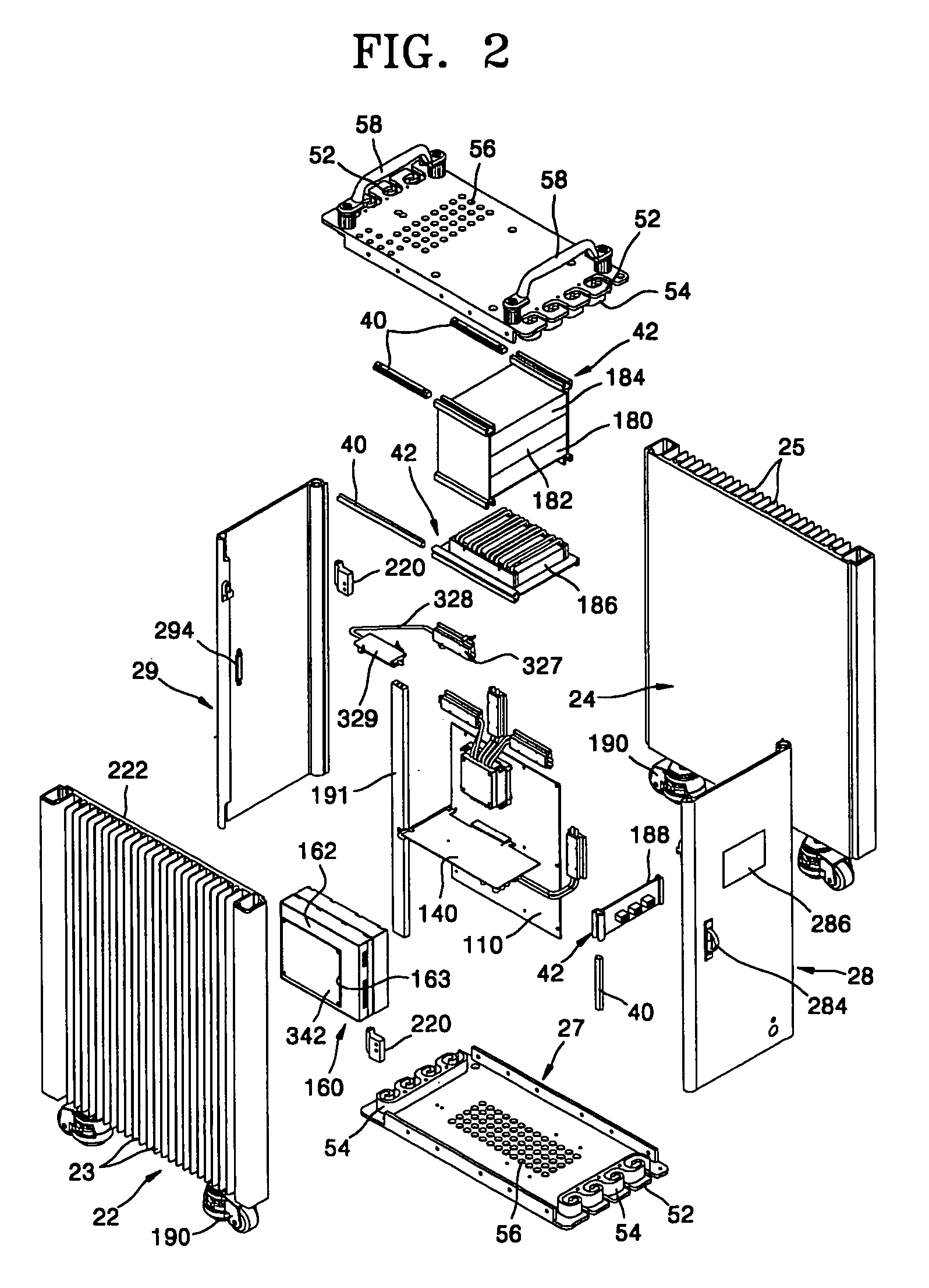
[0044]A computer according to the present invention is illustrated in FIGS. 1 through 9.

[0045]Referring to FIGS. 1 and 9, a computer 1 according to the present invention includes a plurality of parts 10 and a case accommodating the parts 10. Some of the parts generate heat when the computer 1 operates. The case includes a plurality of plates. In this embodiment, the case has a hexahedral shape and the plurality of plates includes a left plate 22, a right plate 24, an upper plate 26, a lower plate 27, a front plate 28, and a rear plate 29. Each of the plates has a thickness of about 5–7 mm. Examples of heat generating components installed in the case include a central processing unit (CPU) 120, a graphics card 140, and a power supply 160. Heat generated by the heat generating components is transmitted to the case via heat conduction units and externally dissipated.

[0046]The left plate 22, which forms the left wall of the case, is made of aluminum having a great thermal conductivity u...

second embodiment

[0099]FIG. 10 is a partial cutaway perspective view of the computer 1a according to the present invention. FIG. 11 is an exploded perspective view of the computer 1a of FIG. 10, FIG. 12 is a top view of the computer 1a of FIG. 10, in which an upper plate is not shown, and FIG. 13 is a sectional view taken along line A—A of FIG. 10.

[0100]The computer 1a according to the present invention includes a case accommodating heat generating components. The case is comprised of a plurality of plates, i.e., the left plate 22, the right plate 24, the upper plate 26, the lower plate 27, the front plate 28a, and the rear plate 29a. Examples of heat generating components installed in the case include a CPU 120, a graphics card 140, and a power supply 160. Heat generated by the heat generating components is transmitted to the plates of the case via heat conduction units and externally dissipated.

[0101]The left plate 22 and the right plate 24 are similar to those in the first embodiment. In other wo...

third embodiment

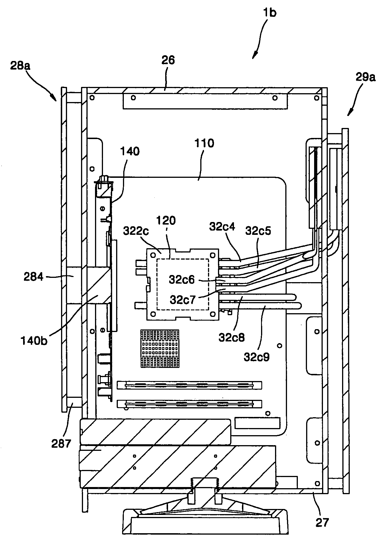
[0118]A computer 1b according to the present invention is illustrated in FIGS. 14 through 17.

[0119]The computer 1b according to the third embodiment of the present invention differs from the computer 1a according to the second embodiment of the present invention in that each of a left plate 22b and a right plate 24b is comprised of a main body portion and a heat dissipating plate portion and has a different heat conduction structure via which heat is transmitted from a heat generating component thereto.

[0120]Hereinafter, the computer 1b according to the third embodiment of the present invention will be described in detail. A detailed description of components in the third embodiment included in the second embodiment will be omitted. For parts of the computer 1b that are not described here, the above descriptions of the corresponding parts to those in the computer 1b can be referred to. Elements of the computer 1b that function in the same way as in the computer 1a are denoted by the...


PUM


Abstract

Provided is a computer with a case and a plurality of parts, including heat generating components that generate heat when operated, installed in the case, wherein the case includes a plurality of plates, and heat generated by at least one of the heat generating components when operated is transmitted to at least one of the plates via a heat conduction unit, which connects the at least one of the heat generating parts and the plate, and externally dissipated from the case. The heat generating components mounted in the case can be noiselessly and efficiently cooled without a noise-generating cooling fan.

Description

BACKGROUND OF THE INVENTION[0001]This application claims the priority of Korean Patent Application No. 2003-30358, filed on May 13, 2003, and No. 2004-27563, filed on Apr. 21, 2004, in the Korean Intellectual Property Office, the disclosures of which are incorporated herein in their entirety by reference.[0002]1. Field of the Invention[0003]The present invention relates to a computer, and more particularly, to a computer in which heat generating components can be noiselessly and efficiently cooled not using cooling fans.[0004]2. Description of the Related Art[0005]In general, computers are comprised of a variety of functional parts. Representative examples of functional parts that may be installed in a computer case include a main board, a central processing unit (CPU), a graphics card, a sound card, a power supply, a hard drive, a floppy disk drive, a CD-ROM drive, a DVD-ROM drive, etc. These internal parts installed in the computer case are connected to external peripheral devices...

Claims


Application Information

Patent Timeline
Patent Type & Authority Patents(United States)
IPC IPC(8): H05K7/20G06F1/18G06F1/20
CPCG06F1/181G06F1/183G06F1/184H05K7/20409G06F1/188G06F1/20G06F1/187G06F2200/201
Inventor LEE, SANG CHEOL
Owner ZALMAN TECH CO LTD
Learn More