Variable area nozzle

a gas turbine engine and variable area technology, applied in vessel construction, marine propulsion, aircraft navigation control, etc., can solve the problems of increasing the pressure ratio of the nozzle, complex multi-variable devices, and increasing the velocity of the gas stream, so as to minimise the jet velocity, optimise the jet velocity profile, and maximize the effect of airflow

Inactive Publication Date: 2007-02-20
ROLLS ROYCE PLC
View PDF17 Cites 34 Cited by
  • Summary
  • Abstract
  • Description
  • Claims
  • Application Information

AI Technical Summary

Benefits of technology

[0007]Therefore it is an object of the present invention to provide a means for varying the areas of the final exhaust nozzle and the core exhaust exit such that; the final exhaust nozzle area is increased at take-off to maximise airflow and minimise jet velocity; the core exhaust exit area is adjustable during take-off to optimise the jet velocity profile to further reduce jet noise.

Problems solved by technology

If the nozzle comprises fixed convergent-divergent geometry, optimised for cruise, the losses at lower nozzle pressure ratios would increase due to either over expansion of the exhaust gases or exhaust flow separation.
However, these are generally complex multi-variable devices, typically consisting of systems of overlapping petals and comprising numerous moving components and multiple actuation systems.
This increases the velocity of the gas stream and intrinsically disadvantageously increases the amounts of exhaust or jet noise.
Furthermore, at a lower engine power, for instance relatively slow cruise; the centre-body is in its forward-most position where the mixing section is generally divergent in area.
This cruise position leads to a reduced gas stream velocity relative to the ambient air and disadvantageously provides a less thrust-capable engine.

Method used


Image

  • Variable area nozzle
  • Variable area nozzle
  • Variable area nozzle

Examples


Embodiment Construction

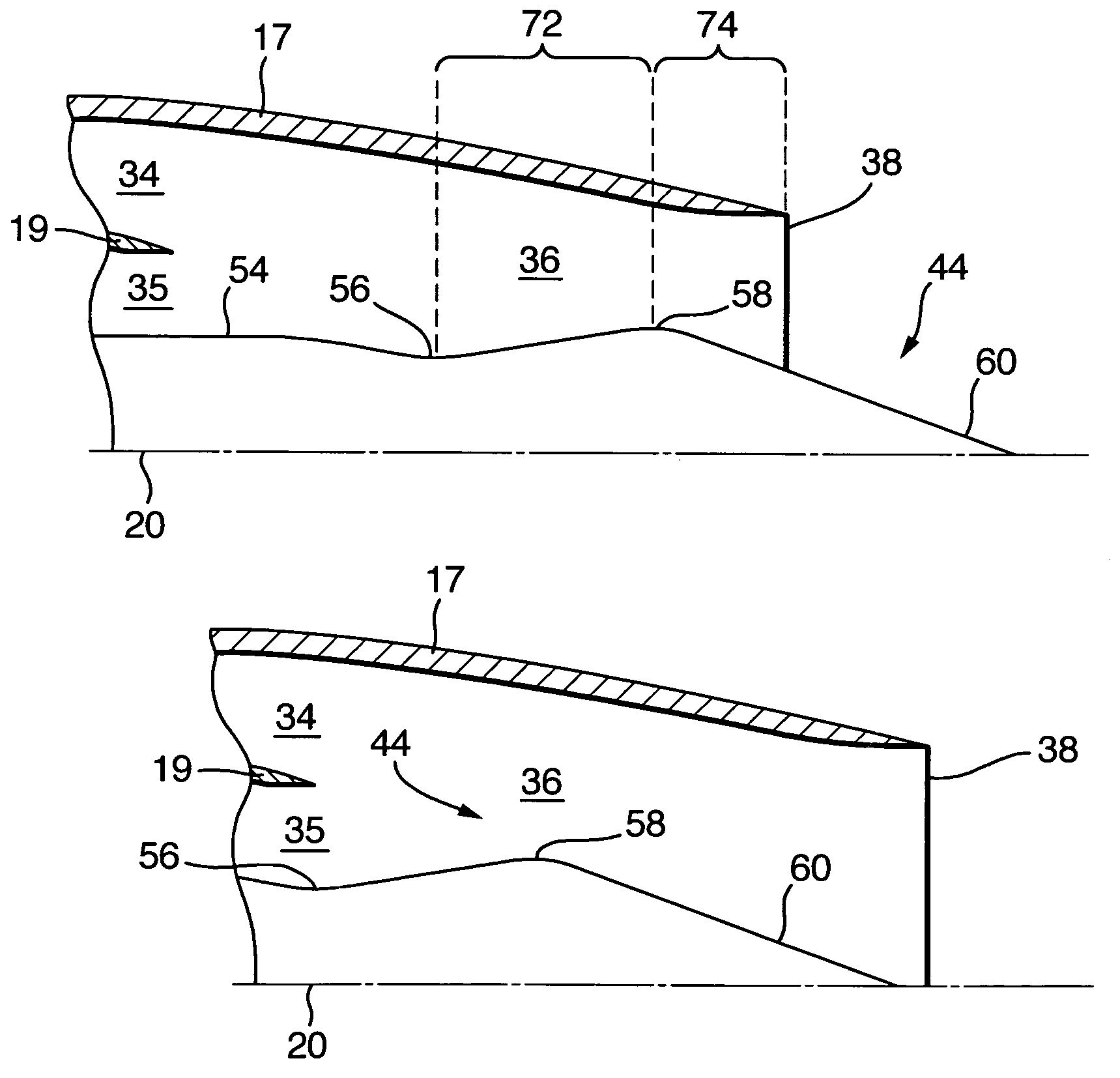
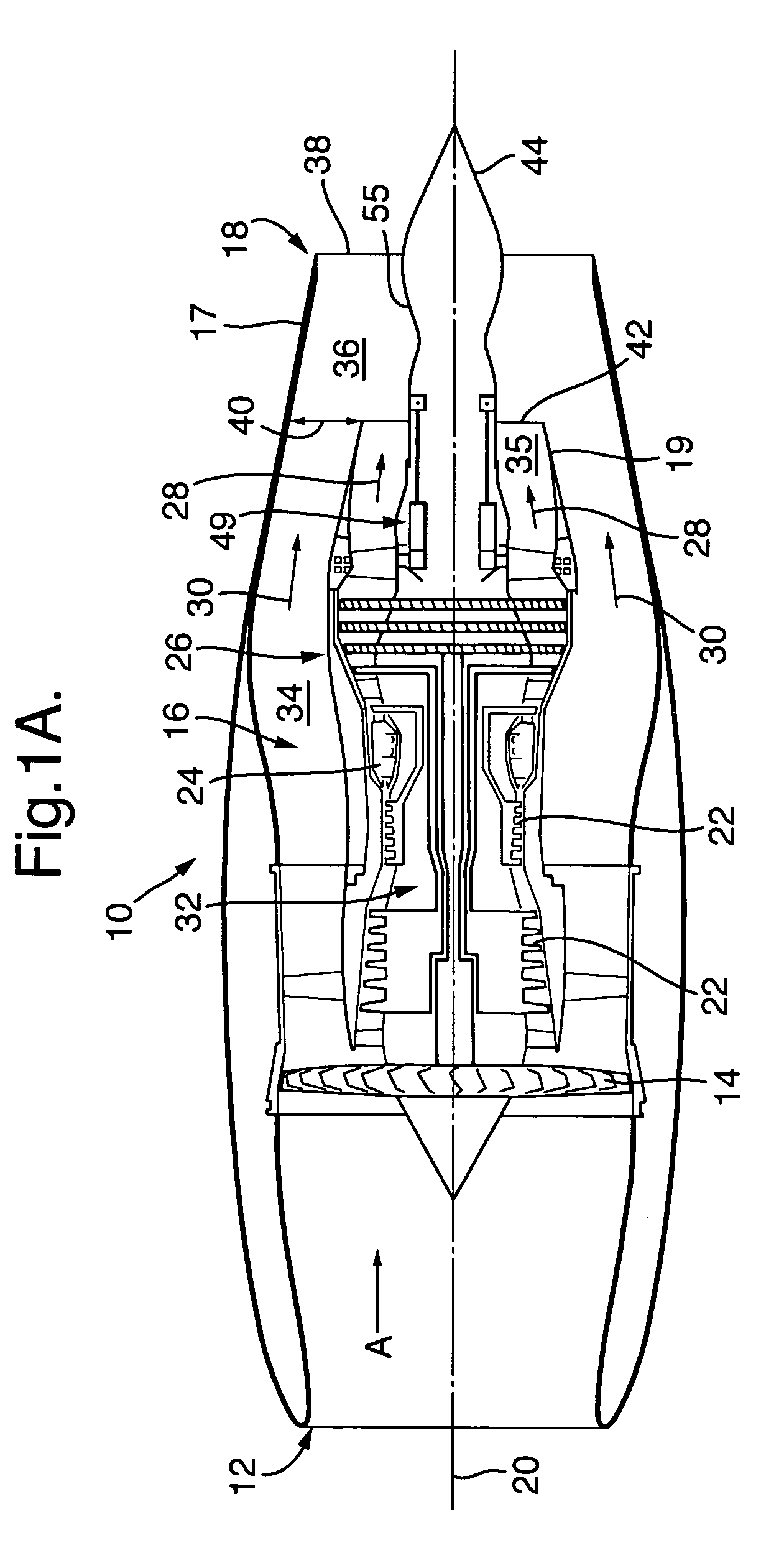
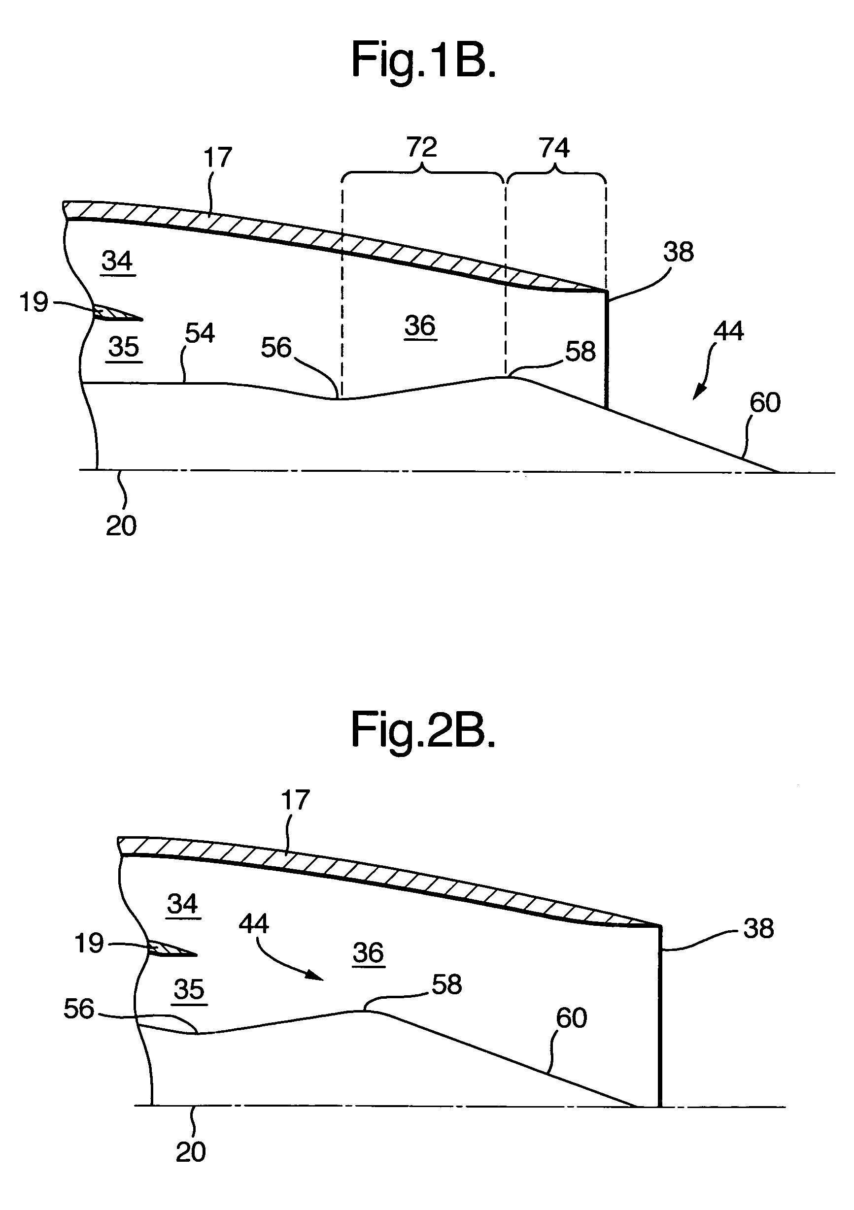
[0031]With reference to FIGS. 1A and 2A where reference numerals of one figure denote like elements of the other figure, a ducted fan gas turbine engine 10 comprises, in axial flow series an air intake 12, a propulsive fan 14, a core engine 16 and an exhaust nozzle assembly 18 all disposed about a main engine axis 20. The exhaust nozzle assembly 18 comprises an outer nozzle 17 and a radially inner nozzle 19. The core engine 16 comprises, in axial flow series, a series of compressors 22, a combustor 24, and a series of turbines 26. The direction of airflow through the engine 10, in operation, is shown by arrow A and the terms upstream and downstream used throughout this description are used with reference to this general flow direction. Air is drawn in through the air intake 12 and is compressed and accelerated by the fan 14. The air from the fan 14 is split between a core engine flow 28 and a bypass flow 30. The core engine flow 28 enters core engine 16, flows through the core engin...


PUM


Abstract

An exhaust nozzle assembly for a gas turbine engine, the assembly comprises a main axis, an inner nozzle, an outer nozzle, a translatable centre-body and an actuator for translating the centre-body between a forward position and a rearward position. The centre-body is disposed radially inwardly of the inner nozzle thereby partly defining an inner duct for a core engine gas flow, an outer duct for a bypass gas flow is defined by the inner nozzle and the outer nozzle. The outer nozzle extends downstream of the inner nozzle and with the centre-body defines a final mixing duct having a final exhaust exit area. When the centre-body is in the forward position the final exhaust exit area is at a maximum area, and when the centre-body is in a rearward position the final exhaust exit area is at a minimum area.

Description

[0001]This application is a continuation of Ser. No. 10 / 383,554 filed on Mar. 10, 2003 now abandoned.FIELD OF THE INVENTION[0002]The present invention relates to a variable exhaust area nozzle for a gas turbine engine.BACKGROUND OF THE INVENTION [0003]An aircraft is required to perform many different operational modes in a single flight cycle. Such modes comprise taxiing, take-off, climb, cruise, holding, decent and landing to which the engines of the aircraft must also comply with related performance requirements.[0004]Conventional gas turbine engines, particularly turbofans, operate at relatively low exhaust nozzle pressure ratios, where it is sufficient to use a convergent nozzle to develop thrust, as the pressure loss due to external expansion of the working exhaust gases is relatively low. With increasing flight speed the nozzle pressure ratio increases, and the expansion of the gases needs to be controlled to reduce losses, normally using a convergent-divergent nozzle. In the ...

Claims


Application Information

Patent Timeline
Patent Type & Authority Patents(United States)
IPC IPC(8): F02K1/00F02K1/08
CPCF02K1/08
Inventor WHURR, JOHN R.
Owner ROLLS ROYCE PLC
Why Eureka
Try Eureka