Parallel fluid processing systems and methods

a technology of parallel fluid processing and fluid flow, applied in the field of fluid processing, can solve the problems of affecting the quality of fluid,

Active Publication Date: 2007-02-20
AGILENT TECH INC
View PDF54 Cites 101 Cited by
  • Summary
  • Abstract
  • Description
  • Claims
  • Application Information

AI Technical Summary

Problems solved by technology

For example, if it is desired to evenly split common supplies of solvents or reagents to multiple process regions, it may be difficult to ensure that each process region receives a substantially equal flow.
The problem may be exacerbated by the presence of solid materials, such as catalysts or separation media, e.g., due to variations in solid particle types, sizes, and / or packing density.
Additional concerns may arise if it is desired to vary the composition of common solvents or reagents over time, since it can be difficult to ensure that each process region is subject to the same supply fluid composition at substantially the same time.
While instrumentation and flow control devices might be added to each process region to address these problems, adding such components can rapidly increase the complexity and cost of parallel fluid processing systems to the point that they are no longer economical to build, operate, or maintain.
Moreover, if microfluidic process regions are used, it can be difficult to accurately measure extremely low fluid flow rates supplied to individual process regions.
In the absence of systems or methods for ensuring that reproducible process conditions are maintained in parallel fluid processing systems, it can be difficult to draw confident conclusions from data obtained from individual process regions in different experimental runs, let alone compare data obtained from multiple process regions in the same experimental run.
As a result, the scientific utility of efficient parallel fluid processing systems appears to be limited.
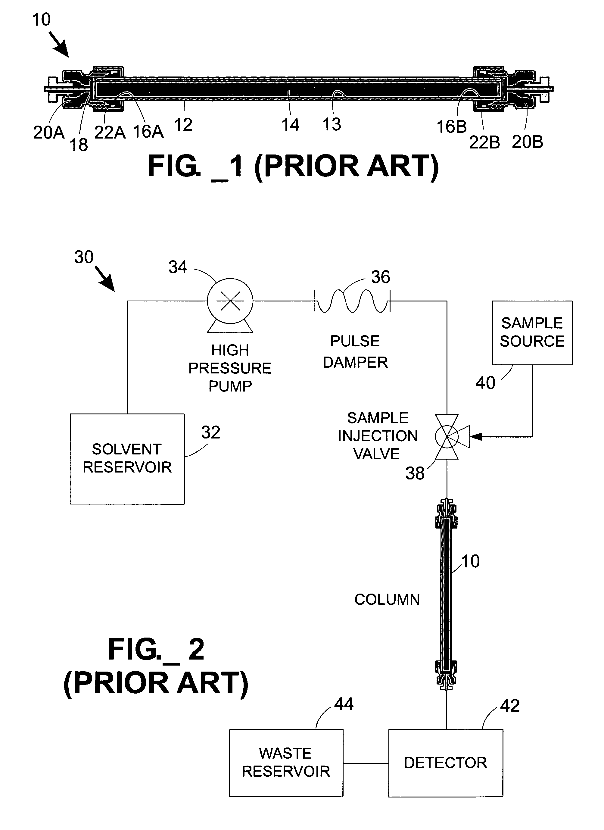
Due to the cost of conventional tubular chromatography columns, they are often re-used for many (e.g., typically about one hundred or more) separations.
However, this time-consuming flushing or cleaning step does not always yield a completely clean column 10.
This means that, after the first separation performed on a particular column, every subsequent separation may potentially include false results due to contaminants left behind on the column from a previous run.
Eventually, columns become fouled to the point that they are no longer useful, at which point they are removed from service.
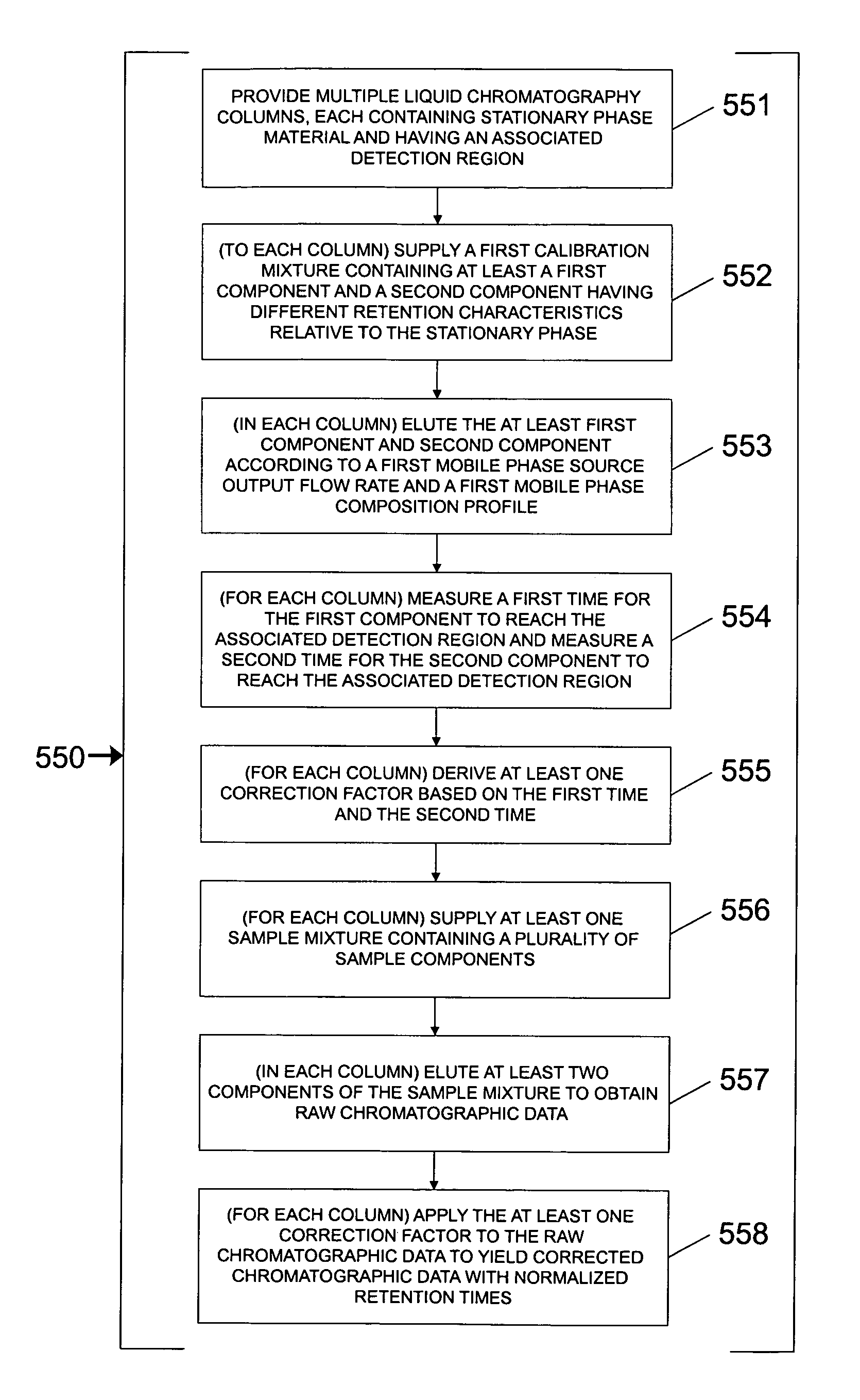
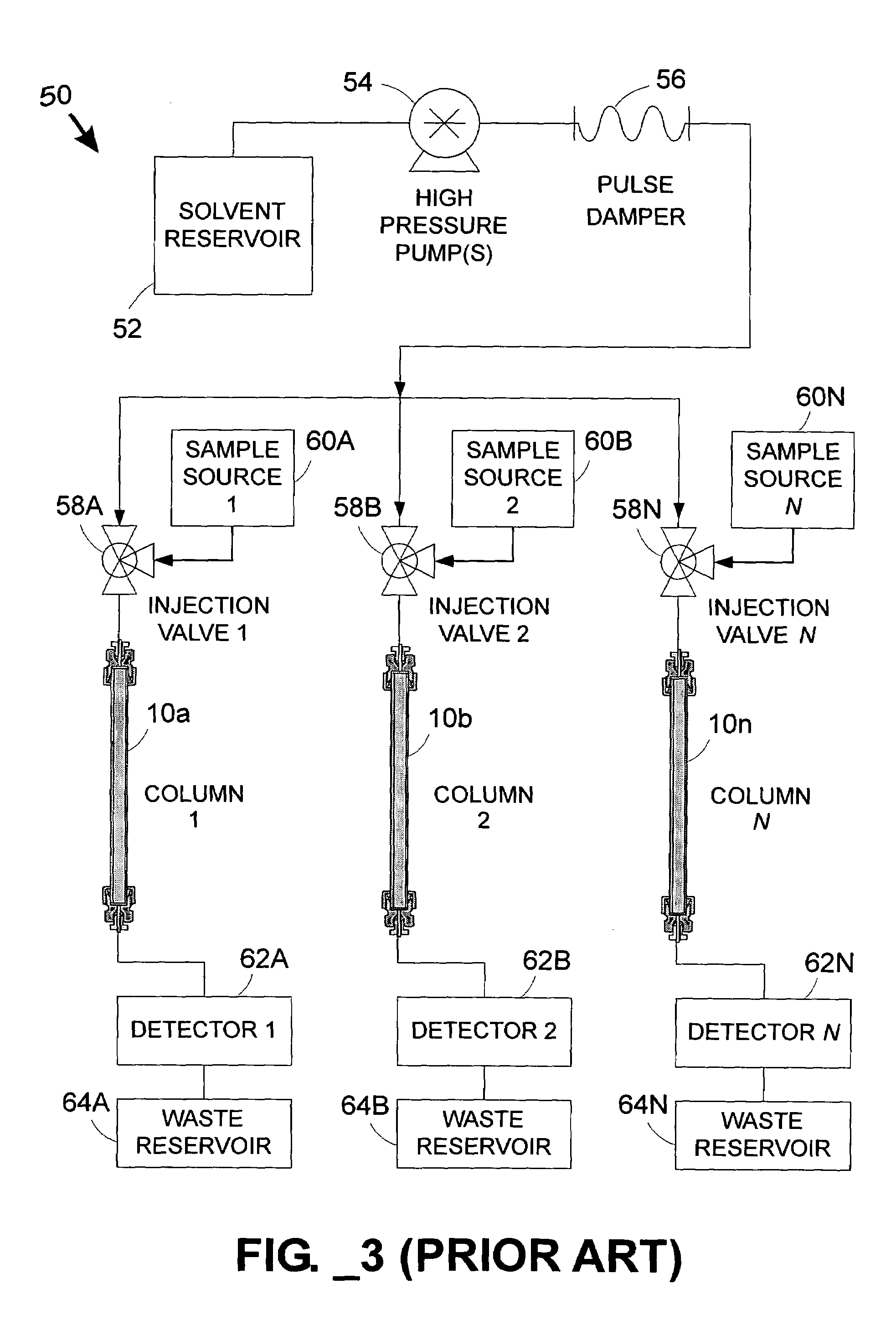
One issue is accounting for different rates of fluid flow through each column in a multi-column system, particularly in low-flow environments not well-suited for inferential flow measurement.
When a common pump supplies multiple columns (e.g., columns 10A, 10B, 10N, 145A–145X, or 439A–439X), however, it is difficult to predict the flow through each individual column—even if the columns appear substantially identical—since impedance to fluid flow varies somewhat from one column to another and fluid flow will be biased toward the column(s) with the least fluidic impedance.
That is, even when columns are carefully selected in an attempt to match their impedances, variations between columns will inevitably cause backpressure differences that in turn cause flow rate differences between fluid streams.
To further complicate matters, many commonly employed chromatographic techniques utilize a solvent profile that changes with time.
Thus, in a parallel multi-column system employing a common set of pumps for performing gradient elution, the presence of a changing solvent concentration exacerbates the difficulty of ensuring that identical mobile phase conditions (i.e., including both flow rate and concentration) are provided to each column at the same time.
Pressure ramps are inherently transient conditions, and can lead to unpredictable flow patterns in a common-fluid-supply parallel separation system before steady-state flow conditions are attained.
These unpredictable flow patterns exacerbate column-to-column variability
Due to the difficulty of providing identical mobile phase conditions to each column in a parallel separation system with a common fluid supply, seemingly identical columns tend to perform differently.
As a result of the different performance characteristics of seemingly identical columns in a parallel separation system with a common fluid supply, it is difficult to compare analytical results obtained from one column to another.
As evident from FIG. 9, in which the individual chromatograms from FIG. 8 have been time-shifted to a common retention time for the first unretained peak, a mere phase shift is generally insufficient to eliminate column-to-column variability for the remaining (retained) species.
Since retention times are used to identify species within a sample, variation in retention times from one column to another increases the uncertainty of positively identifying individual species.

Method used


Image

  • Parallel fluid processing systems and methods
  • Parallel fluid processing systems and methods
  • Parallel fluid processing systems and methods

Examples


example

Parallel Chromatography Retention Time Correction System

[0145]While various combinations of elements may be employed in a system for correcting data (e.g., retention times, peak areas, or other desirable values) in multi-column liquid chromatography, one example is provided in FIG. 17. The system 600 includes two solvent reservoirs 601, 602 in fluid communication with a degasser 604 and at least one (more preferably at least two) pump(s) 605. A pulse damper 608 is preferably provided downstream of true pump(s) 605 to reduce variations in the mobile phase supply pressure. A mixer (not shown) is preferably disposed between the pump(s) and the fluidically linked separation columns. A multi-column separation device 610 (such as the integrated microfluidic devices 100, 400 or fluidically linked conventional columns 10A–10N) may be used. Calibrant or mobile phase may be provided to the separation device 610 through a calibrant / sample supply 618, which may include multiple conventional loo...


PUM

PropertyMeasurementUnit
porosityaaaaaaaaaa
thicknessaaaaaaaaaa
internal pressuresaaaaaaaaaa

Abstract

A parallel fluid processing system including multiple fluid process regions containing solid material in fluid communication with a common first fluid source may be used to conduct analyses and / or synthesis in parallel. A parallel fluid processing data correction method includes supplying and processing a calibrant in each fluid process region, measuring a first physical parameter and deriving at least one correction factor based on the parameter, supplying and processing at least one second fluid in each fluid process region, and then applying the correction factor to yield corrected process data. Retention time correction, peak area correction, and other useful data corrections may be performed. Parallel fluid processing may be performed with microfluidic devices and systems. A system for correcting retention times in parallel liquid chromatography is further provided.

Description

STATEMENT OF RELATED APPLICATION(S)[0001]This application claims benefit of U.S. provisional patent application Ser. No. 60 / 461,846 filed Apr. 10, 2003.FIELD OF THE INVENTION[0002]The present invention relates to fluid processing, such as may be used for synthesizing and / or analyzing various chemical or biological substances.BACKGROUND OF THE INVENTION[0003]Recent advances in various scientific and industrial fields have dramatically increased the desirability of synthesizing new chemical and biological substances, and have similarly increased the need to analyze these substances, e.g., to identify their active components, verify their stability, and optimize processes for their manufacture. In an effort to accelerate these capabilities, researchers have sought to introduce a higher degree of automation to synthetic and analytical processes as well as increase the number of processes performed in parallel. Most of these processes are performed with fluids (e.g., liquids and / or gases...

Claims


Application Information

Patent Timeline
Patent Type & Authority Patents(United States)
IPC IPC(8): G01N30/02B01D15/08
CPCG01N30/466G01N30/8665G01N30/8668G01N30/6095
Inventor GAMBLE, RONALD C.OSECHINSKIY, SERGEY I.
Owner AGILENT TECH INC
Why Eureka
Try Eureka