Enhanced lubrication system for drive axle assemblies

a technology of lubrication system and drive axle, which is applied in the direction of machine/engine, drip or splash lubrication, etc., can solve the problems of reducing the useful life of lubricant, affecting efficiency and fuel economy, and increasing the temperature of lubricant, so as to reduce the churning loss of inventive assembly, reduce the operating temperature of lubricant sump, and reduce the loss of churning loss

Active Publication Date: 2007-02-20
DANA HEAVY VEHICLE SYSTEMS GROUP LLC
View PDF26 Cites 19 Cited by
  • Summary
  • Abstract
  • Description
  • Claims
  • Application Information

AI Technical Summary

Benefits of technology

[0011]A drive axle assembly in accordance with the present invention is advantageous as compared to existing drive axle assemblies. The inventive drive axle assembly uses a collector to reduce churning losses by lowering the dynamic lubricant level in the axle assembly without having a negative impact on lubricant life. The inventive assembly maintains or extends existing lubricant drain intervals because the total amount of lubricant in the axle is maintained. The reduced churning losses of the inventive assembly lower the operating temperature of the lubricant sump. Reduction in churning loss and lubricant sump temperature improves efficiency and fuel economy. In addition to the use of a collector, the inventive assembly also provides a means for filtering contaminants in the lubricant sump. By mounting the filter in the plug for the cover plate opening, repair or servicing of the filter is made easier.

Problems solved by technology

This churning has a negative impact on efficiency and fuel economy and also increases the temperature of the lubricant.
Doing so, however, reduces the useful life of the lubricant thereby increasing required maintenance (including more frequent draining and refilling of lubricant).
Conventional drive axle assemblies also frequently suffer from the introduction of contaminants into the lubricant.
Foundry sand may be present due to insufficient cleaning of the housing before the axle assembly operation.
Further, operation of the assembly can cause particles of metal to be introduced into the lubricant.

Method used


Image

  • Enhanced lubrication system for drive axle assemblies
  • Enhanced lubrication system for drive axle assemblies
  • Enhanced lubrication system for drive axle assemblies

Examples


case 48 retains

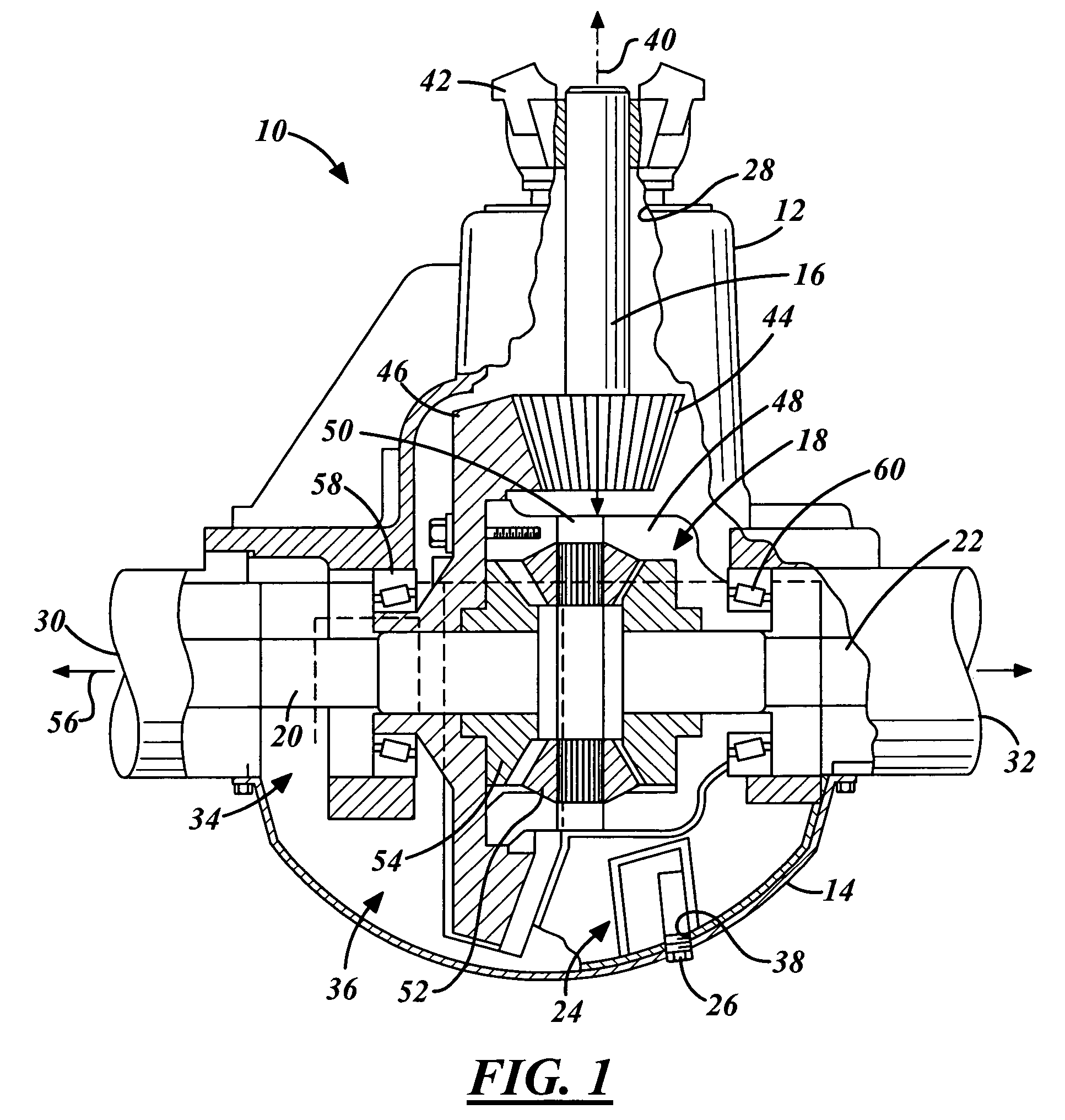
[0023]Case 48 retains and supports spider 50 and gears 52, 54. Case 48 is conventional in the art and rotates with ring gear 46. Case 48 is supported for rotation within housing 12 by bearings 58, 60.

[0024]Spider 50 provides a mounting arrangement for differential gears 52 and is conventional in the art. Spider 50 is supported within case 48 for rotation therewith in ways customary in the art.

[0025]Differential gears 52, 54 transmit torque to axle half shafts 20, 22. Gears 52, 54 are conventional in the art and may comprise conventional bevel gears. Gears 52 are mounted on the arms of spider 50 in a conventional manner and are driven by ring gear 46. Side gears 54 transmit torque from gears 52 to axle half shafts 20, 22. Gears 54 are disposed about axis 56 and are coupled to axle half shafts through a spline connection or in other ways customary in the art.

[0026]Shafts 20, 22 drivingly support wheels (not shown) on either side of drive axle assembly 10. Shafts 20, 22 are conventiona...


PUM


Abstract

An improved lubrication system for drive axle assemblies is provided that uses a collector in connection with a filter plug to lower the dynamic lubricant level in the drive axle assembly and filter contaminants in the lubricant sump. The collector is affixed to a cover plate attached to the drive axle housing and defines a well and a flow passage proximate the bottom of the well. The flow passage is aligned with an opening through which lubricant is inserted into the housing. A plug with a filter is inserted through the opening in the cover plate and into the flow passage. The invention reduces churning losses by lowering the dynamic lubricant level in the axle assembly without having a negative impact on lubricant life.

Description

BACKGROUND OF THE INVENTION[0001]1. Field of the Invention[0002]The present invention relates to drive axle assemblies, and more particularly, to a drive axle assembly with structure designed to improve drive axle lubrication.[0003]2. Discussion of Related Art[0004]Most vehicles include one or more drive axle assemblies. A conventional drive axle assembly includes a pair of axle half shafts extending from a housing on which one or more wheels of a vehicle are mounted. The axle half shafts in the drive axle assembly are driven by a wheel differential disposed within the housing. The wheel differential includes a pinion gear in mesh with a ring gear (which in turn drives a plurality of bevel gears to cause rotation of the axle half shafts).[0005]The drive axle assembly housing commonly has a front opening to allow for connection of an input shaft with an exterior yoke or flange which is in turn connected with a drive shaft of the vehicle. The input shaft powers the pinion gear of the ...

Claims


Application Information

Patent Timeline
Patent Type & Authority Patents(United States)
IPC IPC(8): F16H57/02F16H57/04
CPCF16H57/0447F16H48/08F16H57/0404F16H57/0409Y10T74/2186F16H57/0457F16H57/0483Y10T74/2188F16H57/045
Inventor TURNER, GARY A.WENSTRUP, LEO
Owner DANA HEAVY VEHICLE SYSTEMS GROUP LLC
Why Eureka
Try Eureka