
Sliding roof system

a roof system and sliding technology, applied in the direction of roofs, superstructure subunits, mechanical equipment, etc., can solve the problems of reducing the headroom in the interior of the vehicle, and the system is relatively complicated, and achieves low tolerance, low cost, and simple construction.

Active Publication Date: 2007-02-20
ROOF SYST GERMANY
View PDF10 Cites 28 Cited by
  • Summary
  • Abstract
  • Description
  • Claims
  • Application Information

AI Technical Summary

Benefits of technology

"The invention is a sliding roof system that includes a first lifting lever and a second lifting lever for controlling the lifting motion of the cover. The first lifting lever is connected to the carriage with a slotted piece guide, which allows for a simple and cost-effective construction. The second lifting lever allows for full control over the lifting motion of the cover without any intermediate levers or complicated transmissions. The technical effects of the invention include improved efficiency and control over the lifting motion of the cover."

Problems solved by technology

In order to obtain a particularly large travel, the guide rail has to be constructed to have an increased height, which in turn results in a reduced headroom in an interior of the vehicle.
These systems, however, are relatively complicated.

Method used


Image

  • Sliding roof system
  • Sliding roof system
  • Sliding roof system

Examples


Embodiment Construction

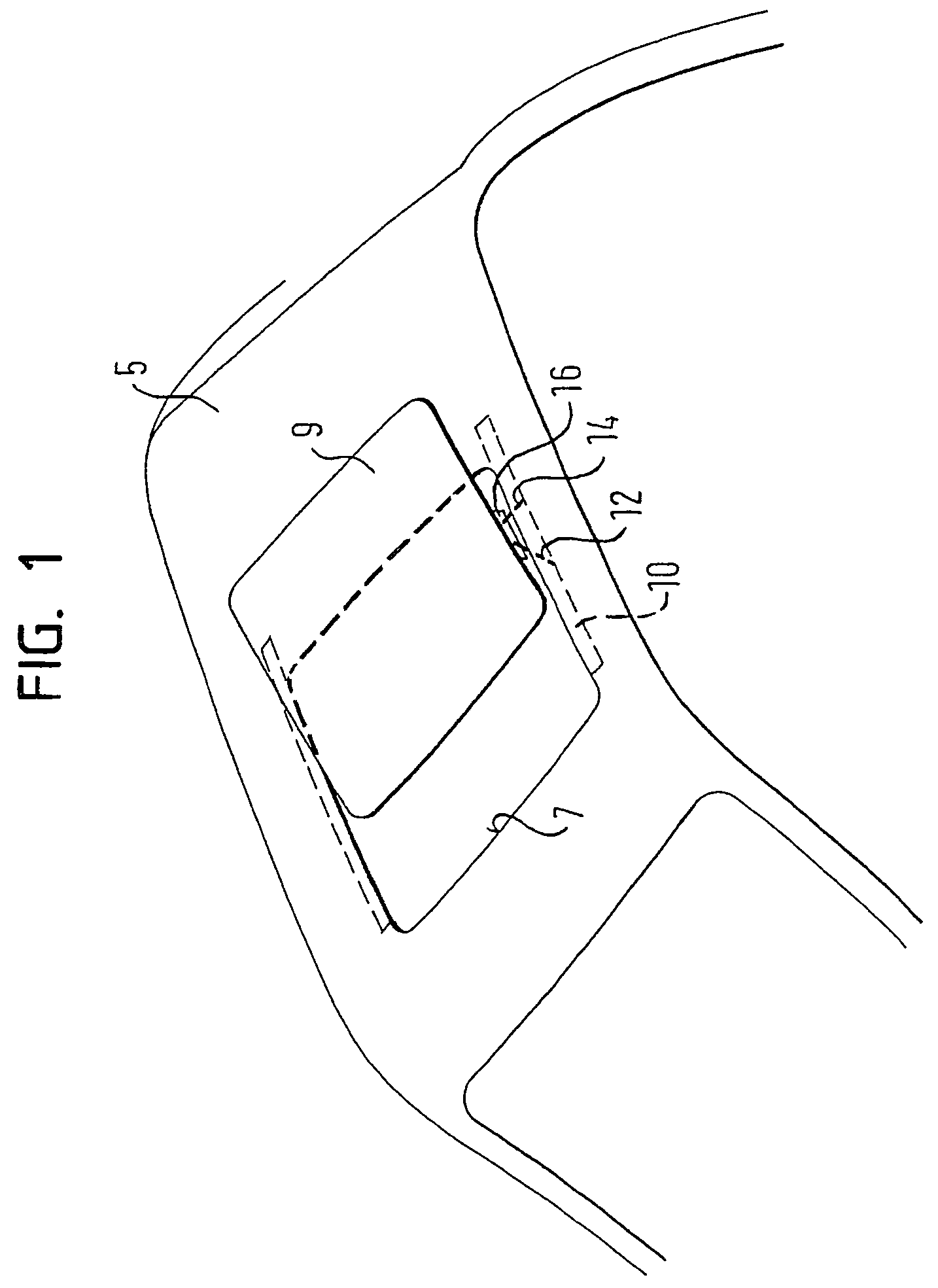
[0022]FIG. 1 shows a vehicle roof 5 with an opening 7. Associated with the opening 7 is a cover 9 that can be moved between a closed position in which the cover 9 closes the opening 7, and an open position that at least partially exposes the opening 7. Associated with the cover 9 is a sliding roof system, the essential components of which include two guide rails 10, first and second lifting levers 12, 14, and two cover supports 16. The cover supports 16 are configured as separate components that are fixedly mounted to the cover 9. Nevertheless, the cover supports 16 may also be constituted by inlay parts, which are embedded in the cover 9, or constituted by fastening tabs that are formed in one piece with the cover 9, etc.

[0023]The two guide rails 10 extend along longitudinal edges of opening 7, i.e., extend along a longitudinal direction of travel of a vehicle, from front to rear. Usually the guide rails 10 are formed by a section made of an aluminum alloy. A carriage 18 (see FIG. ...


PUM


Abstract

A sliding roof system includes at least one guide rail, a carriage shiftable in the guide rail, and a cover support coupled with the carriage. The cover support is adapted to be attached to a cover that is movable to open and close a roof opening. A first lifting lever has one end connected to the cover support and another end connected to the carriage with guide pieces received within slots formed in the carriage.

Description

BACKGROUND OF THE INVENTION[0001]The application claims priority to German Application No. 10 2004 018 461.5, which was filed on Apr. 16, 2004.[0002]The invention relates to a sliding roof system comprising at least one guide rail, a carriage shiftable in the guide rail, and a cover support adapted for attachment to a cover and coupled with the carriage.[0003]Sliding roof systems for vehicles are generally known. These sliding roof systems are capable of shifting at least one cover (made from sheet metal, plastics or glass, for instance) between a closed position and an open position. In the closed position, an opening in a vehicle roof will be closed. When the cover is in the open position, the opening will be at least partially exposed.[0004]All sliding roof systems in which the cover is shifted outwardly, such that the cover lies on an outer surface of the vehicle roof in the open position, share a common feature regarding travel and height. It is desirable to provide as much out...

Claims


Application Information

Patent Timeline
Patent Type & Authority Patents(United States)
IPC IPC(8): B60J7/057B60J7/02B60J7/043
CPCB60J7/024
Inventor OECHEL, HOLGER
Owner ROOF SYST GERMANY
Learn More