Ophthalmic lenses with induced aperture and redundant power regions

a technology of induced aperture and power region, applied in the field of ophthalmic lenses, can solve the problems of loss of accommodative ability, inconvenient two modes, and the success of intra-ocular lenses and corneal lenses that are positioned on or in the eye (proximal lenses), and achieve the effects of enhancing vision, rapid power change, and enhanced vision effect of induced apertur

Inactive Publication Date: 2007-02-20
VISIONEERING TECH INC
View PDF4 Cites 62 Cited by
  • Summary
  • Abstract
  • Description
  • Claims
  • Application Information

AI Technical Summary

Benefits of technology

[0011]The present invention defines single focus and multifocal ocular lenses providing optical power for correcting vision over a continuous range from infinity to near sight distances. In a lens power distribution, radial optical steps are introduced having rapidly changing power. The optical steps produce enhanced vision in part by inducing an effective aperture, the image through which the cortical elements of the vision system are induced to concentrate. The enhanced vision effect of the induced aperture is applied to single focus and multiple focus lenses. One or more apical and / or annular induced apertures are used in various configurations to address specific correction requirements. In each configuration, the various induced apertures may have common or distinct minimum or maximum powers in the power distribution. Each such distinct power addresses correction for a specific plane-of-regard. In addition, the repeated nature of the power distribution provides redundant correction points within the optical steps which are integrated by the cortical system to increase acuity for intermediate distances distinct from the planes-of-regard addresses by the induced apertures. In this way, continuous correction may be provided by the inventive lens.
[0012]In certain embodiments, the optical surface shape producing the induced aperture power distribution also reduces spherical aberrations over conical shaped lenses adding to the enhanced vision effect. In one such embodiment, a positive lens having a single annular induced aperture is applied as a enhanced vision single focus lens.

Problems solved by technology

Although the process goes unnoticed for the better part of four decades, the lens body expands in girth and hardens, losing the ability to change shape with a resulting loss in accommodative ability.
Although multifocal spectacle lenses have been largely successful in satisfying the needs of spectacle wearers, multifocal lenses that are positioned on or in the eye (proximal lenses): contact lenses, intra-ocular lenses and the alternative surgically imparted corneal lenses have been much less successful.
These two modes are very inconvenient, and sometimes hazardous to the wearer.
Previous attempts to provide multifocal power to the human eye using contact lenses or other proximal lenses (those on or in the eye) have had limited success.
Though this approach has had considerable success, most designs can correct only moderate amounts of presbyopia and are usually most successful when the surface shape treatment is applied to the corneal side of rigid gas-permeable contact lenses.
In these designs, extreme curvatures are applied to the base curve, often creating metabolic problems for the cornea.
Unfortunately, the spherical zones are pieced together and are not a continuous array or radii with continuous first and second derivatives, with the result that diffraction will play a roll in degrading the optical performance of these lenses.
Though highly effective in generating variable foci, lenses designed around conic shapes do not always provide acceptable optics for the eye and can be somewhat unwieldy when used with interconnecting lens surfaces.
Distance vision suffers from diffractive effects caused apparently by the centermost rings that surround the distance power zone, and by the loss of light and optical clarity created by the grooves between radii.
Unfortunately, the optical areas taken up by these transitions are at best wasted for vision correcting benefit and typically still introduce unfocused regions that reduce overall visual clarity.
Optical discontinuities and ineffective transitions are particularly problematic within or adjacent to lens regions used for distance vision where they are more perceptible to the user than within near vision regions.
Clear distance vision requires clear optics and the preponderant myopic population will not tolerate distance blur.
Although benefits can be gained for correcting presbyopia, most of these designs suffer from defects caused by diffraction at the edge of a dark ring or masked area, a phenomenon that detracts from any possible improvement obtained from these small aperture designs.
In addition, the perimeter masking that is used to create these devices precludes multifocal functioning that is desired for correcting presbyopia.
Lenses made according to the above mentioned patents and methods reflect the optical limitations resulting from a large number of requirements for clear human vision at all distances and under a wide range of light conditions.

Method used


Image

  • Ophthalmic lenses with induced aperture and redundant power regions
  • Ophthalmic lenses with induced aperture and redundant power regions
  • Ophthalmic lenses with induced aperture and redundant power regions

Examples


Embodiment Construction

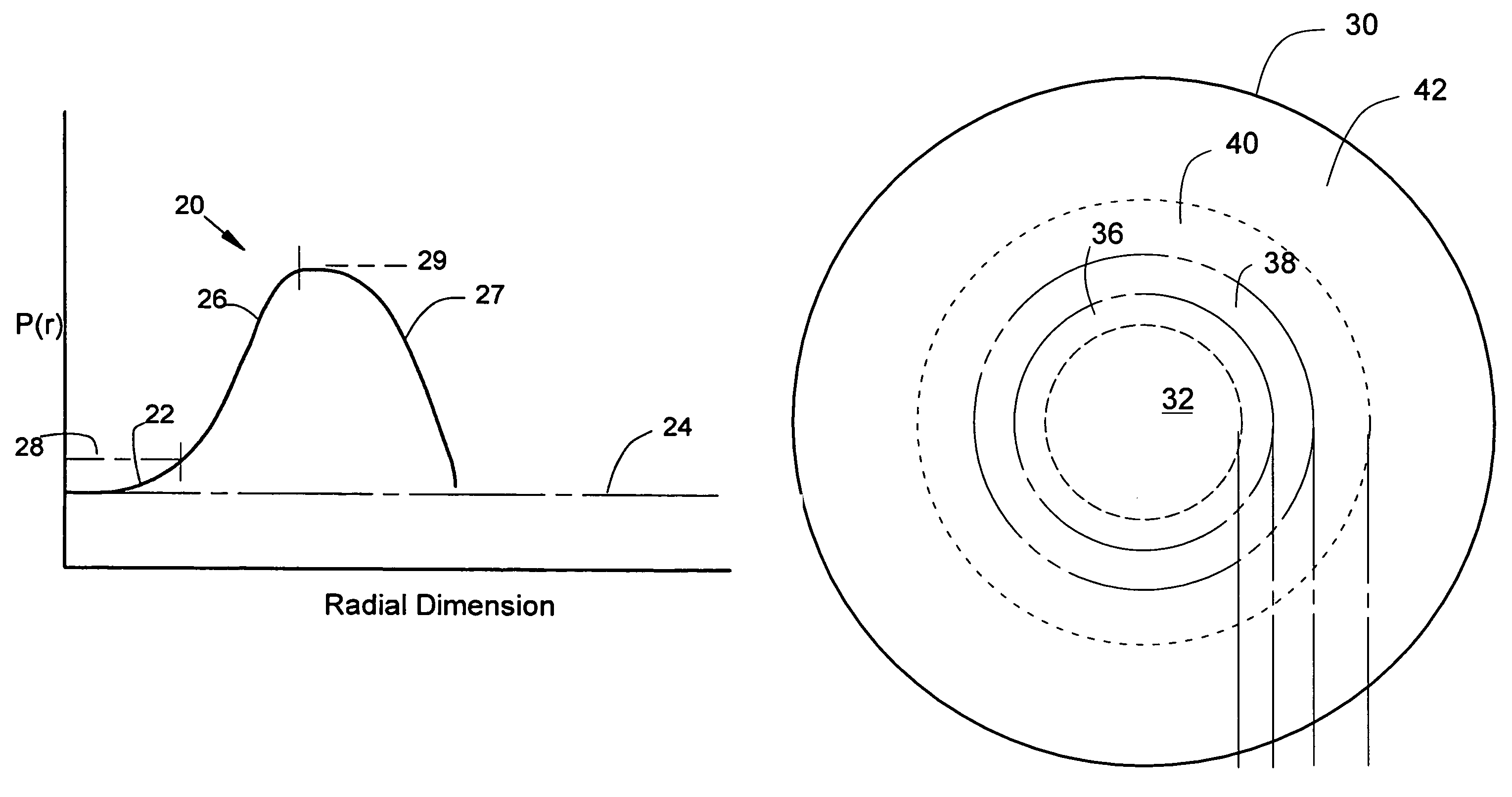
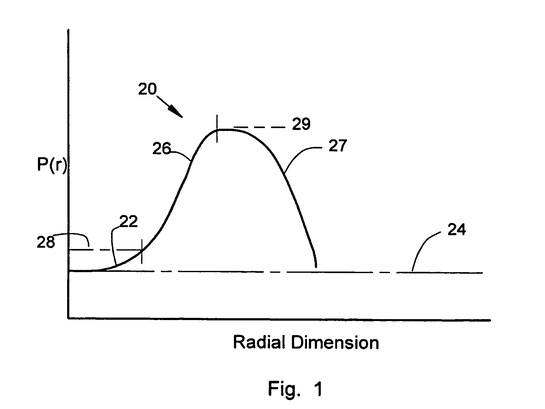
[0030]FIG. 1 depicts a plot of the local optical power distribution 20 as a function of radial dimension from an apex of one embodiment of the invention. The vertical axis is optical power P(r) while the horizontal axis is radial dimension from the apex. A centrally located distance vision region 22 has a distance correction power which is effectively approximated by the apical power 24. The distance correction power is that power required to correct vision for viewing of objects infinitely distant. The required distance correction power may vary with the specific requirements of the users. Focal power increases gradually with increasing radius in the distance vision region 22 until a design level power 28 is reached. The incremental power addition from the apical power 24 (distance vision power) to the power addition that causes blur at the entrance pupil margin is defined here as the design level 28. The incremental power that causes blur in most persons is found to be between +0....


PUM


Abstract

Multifocal and single focus lenses are defined by nonconical aspheric optical surfaces. Various alternative surface shapes provide one or more vision regions bounded by optical steps. Each optical step has rapidly and smoothly changing power in the radial direction which creates an induced aperture through which the cortical elements of the human vision system are induced to concentrate. The induced aperture results in increased clarity and enhanced vision. In various configurations, the induced aperture decreases spherical aberration to further enhance vision. To increase correction intensity at one or more powers, redundant power regions are provided in repeated optical steps or annular apertures. In several embodiments, the redundant power regions create multiple induced apertures at one or more optical powers directed at one or more vision distances.

Description

RELATED APPLICATIONS[0001]The present application claims priority from, and is a continuation-in-part of, U.S. application having Ser. No. 10 / 234,993 filed Sep. 4, 2002 now abandoned which is a continuation-in-part of both U.S. application having Ser. No. 09 / 657,562 filed Sep. 8, 2000 and issued Nov. 5, 2002 as U.S. Pat. No. 6,474,814 B1 and International application No. PCT / US01 / 28156 filed Sep. 6, 2001.BACKGROUND OF THE INVENTION[0002]The present invention relates to ophthalmic lenses having more than a single focal length. The methods and structures provided are applicable to proximal and spectacle lenses and other lenses for correcting human vision.[0003]The majority of vision-correcting lenses are designed to correct sight solely for distance viewing—with a single focal length. When a person views near objects, the eye accommodates the divergent, rather than parallel, light arriving from the near object. The act of accommodation by the human eye results in a physical change in ...

Claims


Application Information

Patent Timeline
Patent Type & Authority Patents(United States)
IPC IPC(8): G02C7/04A61F2/16G02C7/02
CPCG02C7/061G02C7/044A61F2/14A61F2/16A61F2/145
Inventor GRIFFIN, RICHARD A.
Owner VISIONEERING TECH INC
Why Eureka
Try Eureka