Pressure-reducing valve and a controller for a blow-molding machine and method thereof

Inactive Publication Date: 2007-02-20
DAVIS STANDARD
View PDF9 Cites 1 Cited by
  • Summary
  • Abstract
  • Description
  • Claims
  • Application Information

AI Technical Summary

Benefits of technology

[0010]The invention is also a process for regulating the pressure of a cylinder that controls the position of a head tooling pin and die assembly in a blow-molding machine and for bypassing the pressure reducing valve in a blow-molding machine. The process for regulating the pressure of a cylinder, that controls the position of a head tooling pin and die assembly in a blow-molding machine and for bypassing the pressure reducing valve in a blow-molding machine, can include the following steps. Extruding a plastic resin and supplying the melted resin into an accumulator head assembly is performed. Accumulating a pre-defined amount of plastic resin in a material accumulation area then occurs. Injecting the melted resin through a pin and die assembly forms a parison in a mold, such as between two hollow mold halves. Then, allowing the pressure supplied to the programming cylinder during the step of forming parision to be high is performed while reducing the pressure supplied to the programming cylinder is performed at all other times.

Problems solved by technology

If contact occurs between the mandrel pin and the die, the high hydraulic pressure at the programming cylinder can damage the mandrel pin, the die, and / or other extrusion head components.
The industry lacks an accurate and safe apparatus and method for preventing accidental contact between and damage of the mandrel pin and the die tooling that is caused by an inaccurate calibration of the position of the programming cylinder in a blow-molding machine.

Method used


Image

  • Pressure-reducing valve and a controller for a blow-molding machine and method thereof
  • Pressure-reducing valve and a controller for a blow-molding machine and method thereof
  • Pressure-reducing valve and a controller for a blow-molding machine and method thereof

Examples


Embodiment Construction

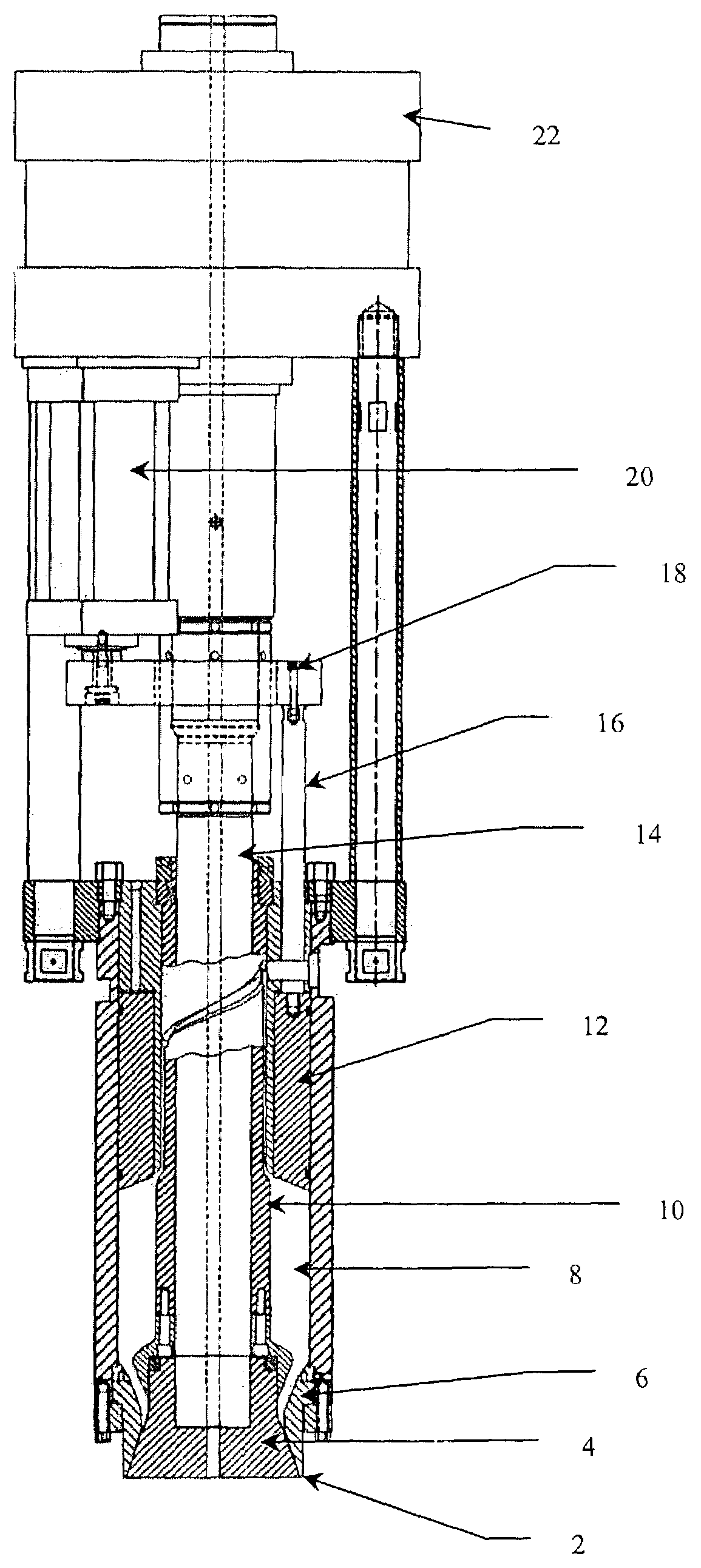
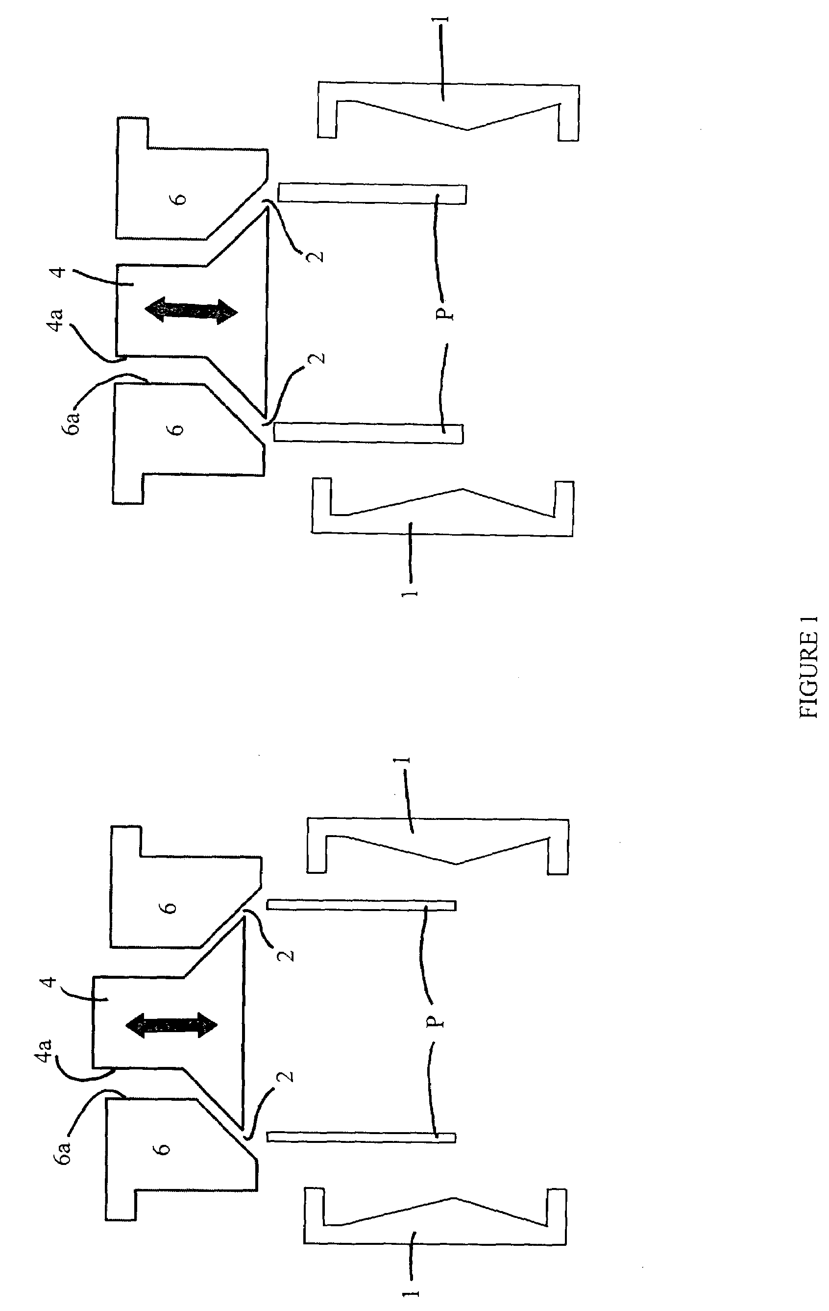
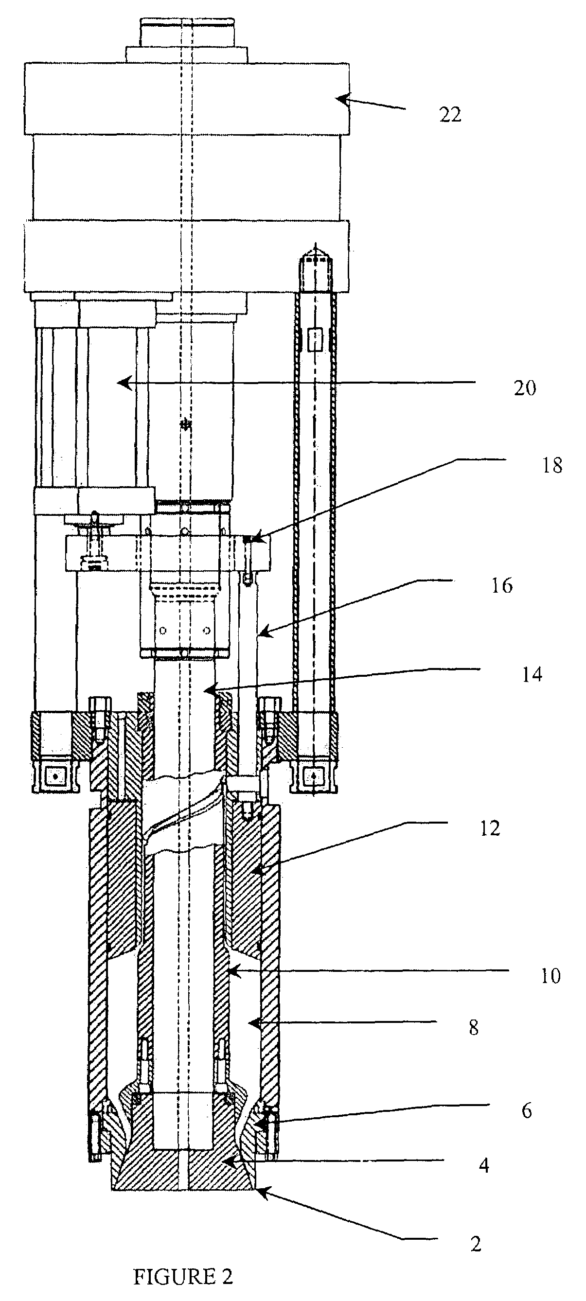
[0015]The invention relates to a pressure reducing valve for reducing the pressure supplied to a head tooling hydraulic positioning valve and a controller for bypassing the pressure reducing valve in a blow-molding machine. A pressure-reducing valve and electrical controller are used to regulate the pressure of a cylinder that controls the position of a head tooling pin and die assembly in a blow-molding machine. The invention is designed such that the pressure is reduced during all time intervals except during a “parison formation” interval of the cycle. This invention greatly reduces the chance of damage to the machine head components due to improper positioning of the mandrel pin and die due to operator error, mechanical electrical error, or hydraulic component failure.

[0016]The invention provides a pressure reducing valve for reducing the pressure supplied to a head tooling hydraulic positioning valve and a controller for bypassing the pressure reducing valve in a blow-molding m...


PUM

PropertyMeasurementUnit
Pressureaaaaaaaaaa

Abstract

The invention is a pressure reducing valve for reducing the pressure supplied to a head tooling hydraulic positioning valve and a controller for bypassing the pressure reducing valve in a blow-molding machine. A pressure-reducing valve and electrical controller are used to regulate the pressure of a cylinder that controls the position of a head tooling pin and die assembly in a blow-molding machine. The invention reduces pressure during all time intervals except during a “parison formation” interval of the cycle. The invention is also a process for regulating the pressure of a cylinder that controls the position of a head tooling pin and die assembly in a blow-molding machine and for bypassing the pressure reducing valve in a blow-molding machine.

Description

BACKGROUND OF THE INVENTION[0001]1. Field of the Invention[0002]The invention relates to a pressure-reducing valve and a controller for a blow-molding machine and method thereof. Specifically, the invention relates to a pressure reducing valve for reducing the pressure supplied to a head tooling hydraulic positioning valve and a controller for bypassing the pressure reducing valve in a blow-molding machine and method for regulating the pressure of a cylinder that controls the position of a head tooling pin and die assembly in a blow-molding machine.[0003]2. Description of Related Art[0004]A mandrel pin and a die arrangement, commonly referred to as a head tooling, are used in an extrusion blow-molding process to form a molten tube of plastic called a “parison.” The parison is extruded from an extrusion head into a hollow mold that is in the shape of the desired product. Once the parison is captured by the mold, the mandrel pin and the die are closed to prevent excess plastic from fl...

Claims


Application Information

Patent Timeline
IPC IPC(8): B29C49/78B29C48/09B29C48/325B29C48/92B29C49/04
CPCB29C47/0023B29C47/92B29C49/4289B29C49/04B29C49/041B29C49/78B29C2947/92514B29C2947/92571B29C2947/926B29C2947/92647B29C2947/92657B29C2947/92809B29C2947/92904B29C2947/92961B29C47/225B29C48/92B29C48/09B29C48/327B29C2948/92514B29C2948/92571B29C2948/926B29C2948/92647B29C2948/92657B29C2948/92809B29C2948/92904B29C2948/92961B29C2049/7871B29C2049/78805B29C49/0005C08G63/60B65D1/00B29K2067/00B29L2031/7126
Inventor D'ANGELO, RUSSELL PHILLIP
Owner DAVIS STANDARD
Why Eureka
Try Eureka