Frequency converter for high-speed generators

a generator and frequency converter technology, applied in the direction of electric generator control, machine/engine, dynamo-electric converter control, etc., can solve the problem that thermal or other sources of energy such as gas turbines cannot generate torque at low speeds, and the ratio of amplitude of alternating voltage between input and output cannot be simple and flexible, so as to achieve low switching losses and simple and flexible

Inactive Publication Date: 2007-02-20
ALSTOM TECH LTD
View PDF26 Cites 62 Cited by
  • Summary
  • Abstract
  • Description
  • Claims
  • Application Information

AI Technical Summary

Benefits of technology

[0005]Therefore an objective of the present invention is to put forward a simple and flexible method that is characterized by low switching losses and that serves to adapt the alternating current generated by a generator and the alternating voltage generated by a generator to a grid. This method is used in conjunction with a generator having at least one excitation coil.
[0007]An aspect of the present invention consists of utilizing the advantages that are typically associated with the use of static frequency converters, namely, simple structure, low switching losses, etc., without having to put up with their disadvantages. A major drawback of static frequency converters is the fact that, even though they allow the frequency to be converted between the input and the output, they typically do not permit a simple regulation of the ratio of the amplitude of the alternating voltage between the input and the output. This drawback has now been overcome in a surprisingly simple manner in that, in order to regulate the power fed into the grid by the generator, on the one hand, the excitation field of the excitation coil of the generator and, on the other hand, the phase angle between the voltage generated by the controlled rectifier and the generator voltage are appropriately regulated.
[0012]The proposed circuit is very suitable for the acceleration procedure. In a simple manner, it can generate any desired voltages or frequencies by being operated at higher switching frequencies. The higher losses associated with this mode of operation only occur during start-up, which is permissible since this is only of short duration and since typically, similar losses occur in a dedicated starting device as well. As soon as the speed range of energy production has been reached, the system switches over to the low-loss basic frequency clocking.
[0013]Therefore, with this circuit, the costs for an additional starting device can be saved.
[0014]According to a first preferred embodiment of the present method, the static frequency converter employed is an indirect frequency converter. In other words, it is a static frequency converter configured as a rectifier / inverter with a direct current stage installed in-between. This simple design—which is normally associated with high switching losses when there is additionally a need to variably adjust the ratio of the voltages between the input and the output by means of a specific switching of the rectifier or inverter—can be achieved without complex measures by using the inventive regulation of the excitation field and by using the phase angle of the voltages generated by the frequency converter.
[0015]Another preferred embodiment of the method according to the invention is characterized in that the adaptation is carried out by means of a static frequency converter with a controlled rectifier in basic frequency clocking and / or with a controlled inverter in basic frequency clocking. The method is especially advantageous when both the rectifier and the inverter are configured as controlled components in basic frequency clocking. The use of two pulse inverters arranged in mirror image so to speak is particularly simple and, owing to the inventive actuation of the excitation coil, is also possible for generators that have to be dynamically controlled in terms of their power connection to the grid.

Problems solved by technology

A major drawback of static frequency converters is the fact that, even though they allow the frequency to be converted between the input and the output, they typically do not permit a simple regulation of the ratio of the amplitude of the alternating voltage between the input and the output.
Thermal or other sources of energy such as gas turbines cannot generate any torque at low speeds.

Method used


Image

  • Frequency converter for high-speed generators
  • Frequency converter for high-speed generators
  • Frequency converter for high-speed generators

Examples


Embodiment Construction

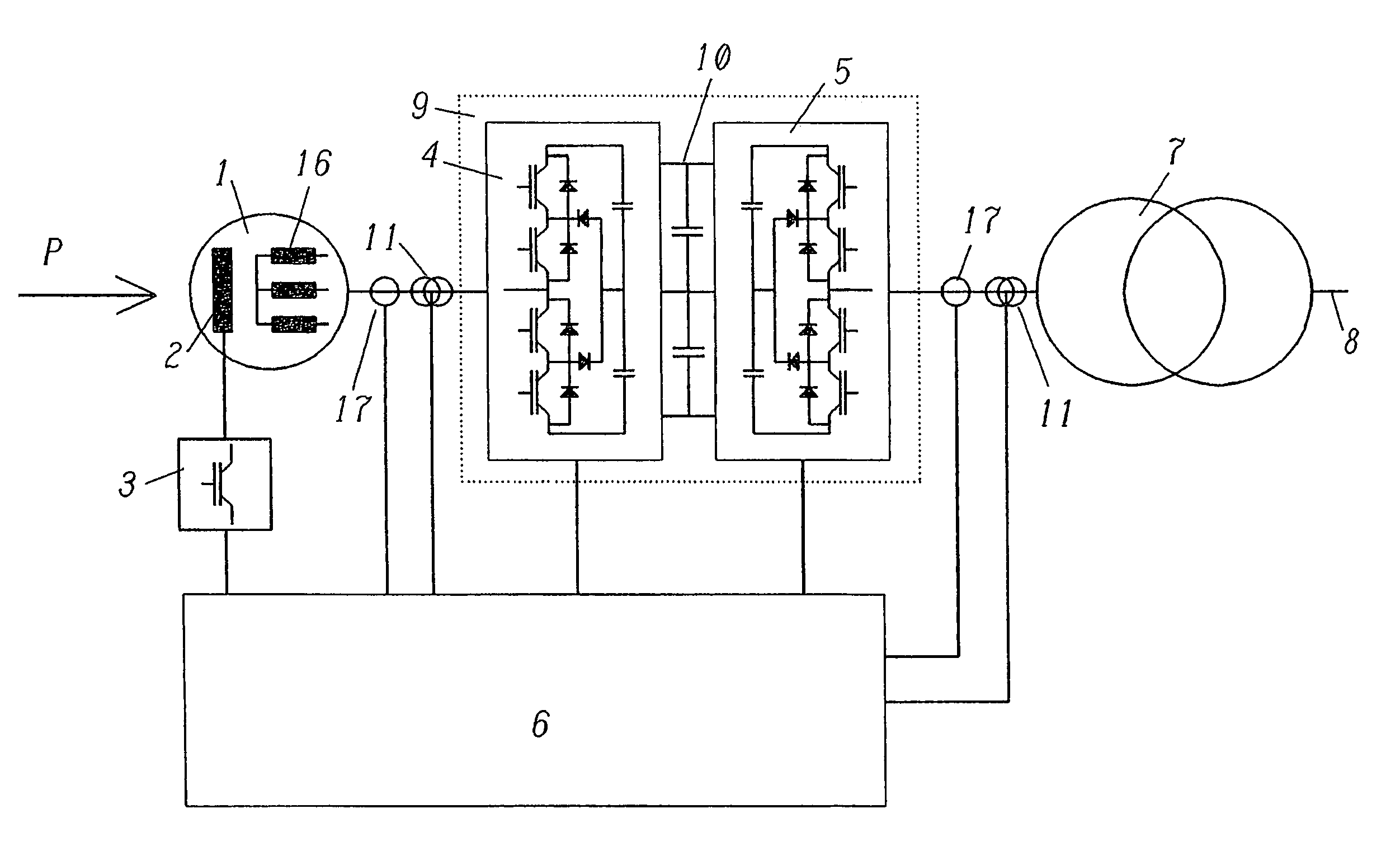
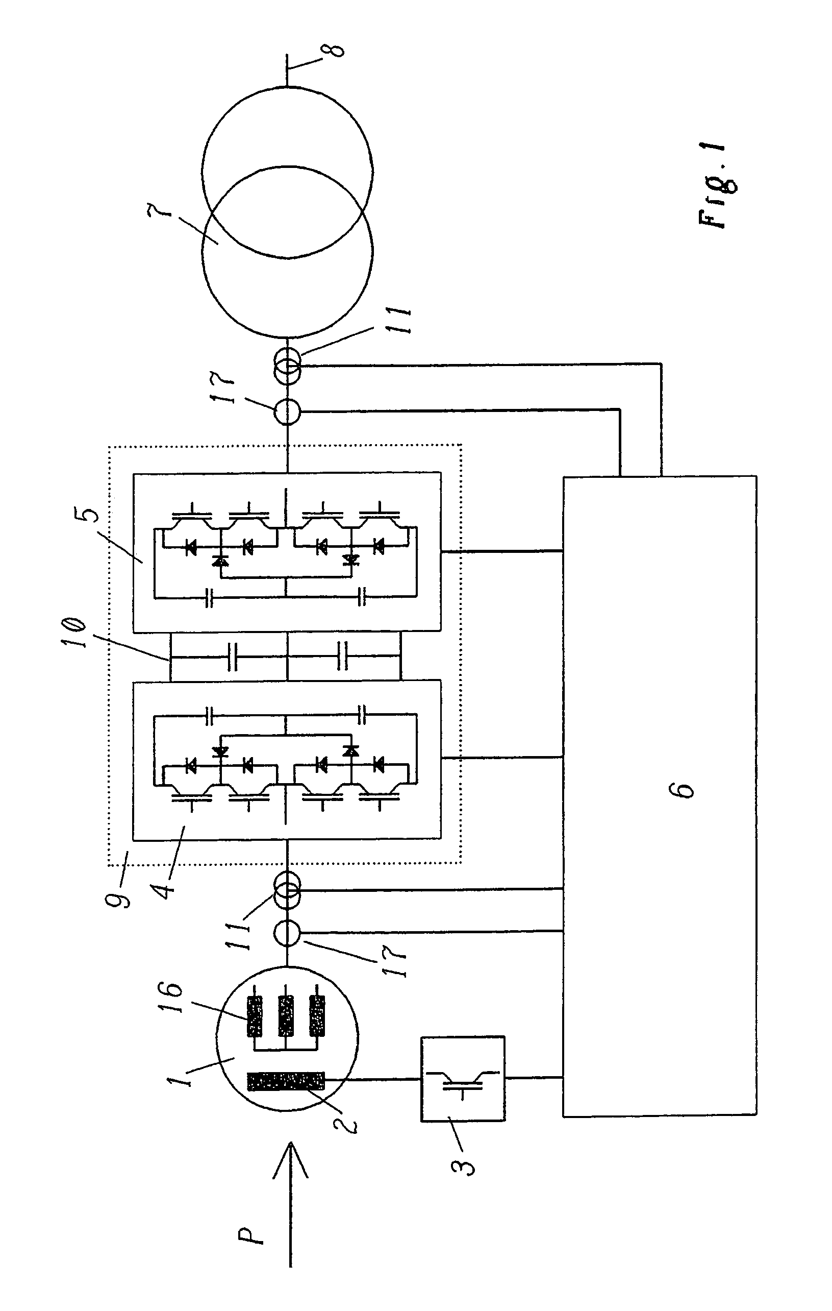
[0030]Many power generation systems make use of thermal or other sources of energy such as gas turbines as the source of power. Typically, such sources of power are characterized by fast rotational speeds and thus by high operating frequencies as well as by the possibility of changing the rotational speed in order to make an adaptation to the power demand.

[0031]In order to take into account the various rotational speeds of the energy generator, which is symbolically represented, for example, in FIG. 1 by the reference letter P, gears, for instance, can be employed between the actual power source P and the generator for generating electric power. Such gears, however, normally have the drawback that they entail high losses and require a great deal of maintenance. Since the rotational frequency of the generator ultimately determines the frequency of the alternating current that is generated with it, as an alternative, it is also possible to connect the generator directly to the source ...


PUM


Abstract

The present invention relates to a method and to a device for adapting the alternating current generated by a generator (1) and the alternating voltage generated by a generator (1) to a grid (8), whereby the generator (1) has at least one excitation coil (2). The power fed into the grid (8) can be flexibly adapted while entailing low switching losses in that a static frequency converter (9) is employed for the adaptation between the generator (1) and the grid (8), and in that, in order to control the power fed into the grid (8), means (3) are provided with which, on the one hand, the strength of the excitation field generated by the at least one excitation coil (2) is regulated and, on the other hand, the phase angle between the frequency converter voltage and the generator or grid voltage is appropriately controlled.

Description

[0001]This application is a continuation of International Patent Application No. PCT / EP04 / 51353, filed on Jul. 5, 2004, which claims priority to German Patent Application No. DE 103 30 473.8, filed on Jul. 5, 2003.FIELD OF THE INVENTION[0002]The present invention relates to a method for adapting the alternating current generated by a generator and the alternating voltage generated by a generator to a grid, whereby the generator is a generator having at least one excitation coil. Moreover, the present invention relates to a device for carrying out such a method.DESCRIPTION OF THE PRIOR ART BACKGROUND[0003]Variable-speed generators or, generally speaking, generators having a frequency that diverges from the grid frequency are typically connected to the electrical power grid by means of converters that adapt the voltage and the frequency being generated by the generator to the voltage and the frequency of the electrical power grid. Various devices are used as converters for this purpos...

Claims


Application Information

Patent Timeline
Patent Type & Authority Patents(United States)
IPC IPC(8): H02P9/44H02J3/38H02M5/458H02P9/30
CPCH02J3/38H02M5/4585H02P9/30H02P2101/10H02M7/487
Inventor RUFER, ALFREDVEENSTRA, MARTIN
Owner ALSTOM TECH LTD
Why Eureka
Try Eureka